Addressing and routing mechanism for web server clusters

a clustering and routing mechanism technology, applied in the direction of securing communication, digital transmission, user identity/authority verification, etc., can solve the problems of difficult management and not scalable solutions

Inactive Publication Date: 2011-10-18
TELEFON AB LM ERICSSON (PUBL)
View PDF1 Cites 6 Cited by
  • Summary
  • Abstract
  • Description
  • Claims
  • Application Information

AI Technical Summary

Benefits of technology

[0020]The scenario of FIG. 4 is a problem from the HIP point of view, because HIP is an end-to-end protocol. In HIP, connections are bound to different HITs at different end-hosts, so, in the FIG. 4 scenario, clients should establish end-to-end connections with the web servers, each having its own HI, and not with the reverse-proxy. However, all servers belonging to the same cluster should have the same cluster identity to allow the cluster to be reachable at a single address and thereby facilitate load balancing by the reverse-proxy.
[0031]All server in the cluster can be identified using a single Host Identity (HI). An administrator can add and remove server from the cluster without having to worry about HI management or DNS updates. From a host point of view, the first host receives only one HI from the DNS that is bound the specific, e.g. web site. The host does not need to care about multiple HIs. This can leave, for example, load balancing work to the reverse-proxy that is responsible for redirecting traffic between different servers behind the reverse-proxy.

Problems solved by technology

The scenario of FIG. 4 is a problem from the HIP point of view, because HIP is an end-to-end protocol.
However, this would be difficult to manage as, whenever a single web server is added to or removed from a cluster, the administrator must update the FQDN—HITs mapping in the DNS.
This is not however a scalable solution, nor is it good from the security point of view as a private key should be stored only in a single location to minimize the risk of revealing the key.

Method used


Image

  • Addressing and routing mechanism for web server clusters
  • Addressing and routing mechanism for web server clusters
  • Addressing and routing mechanism for web server clusters

Examples


Embodiment Construction

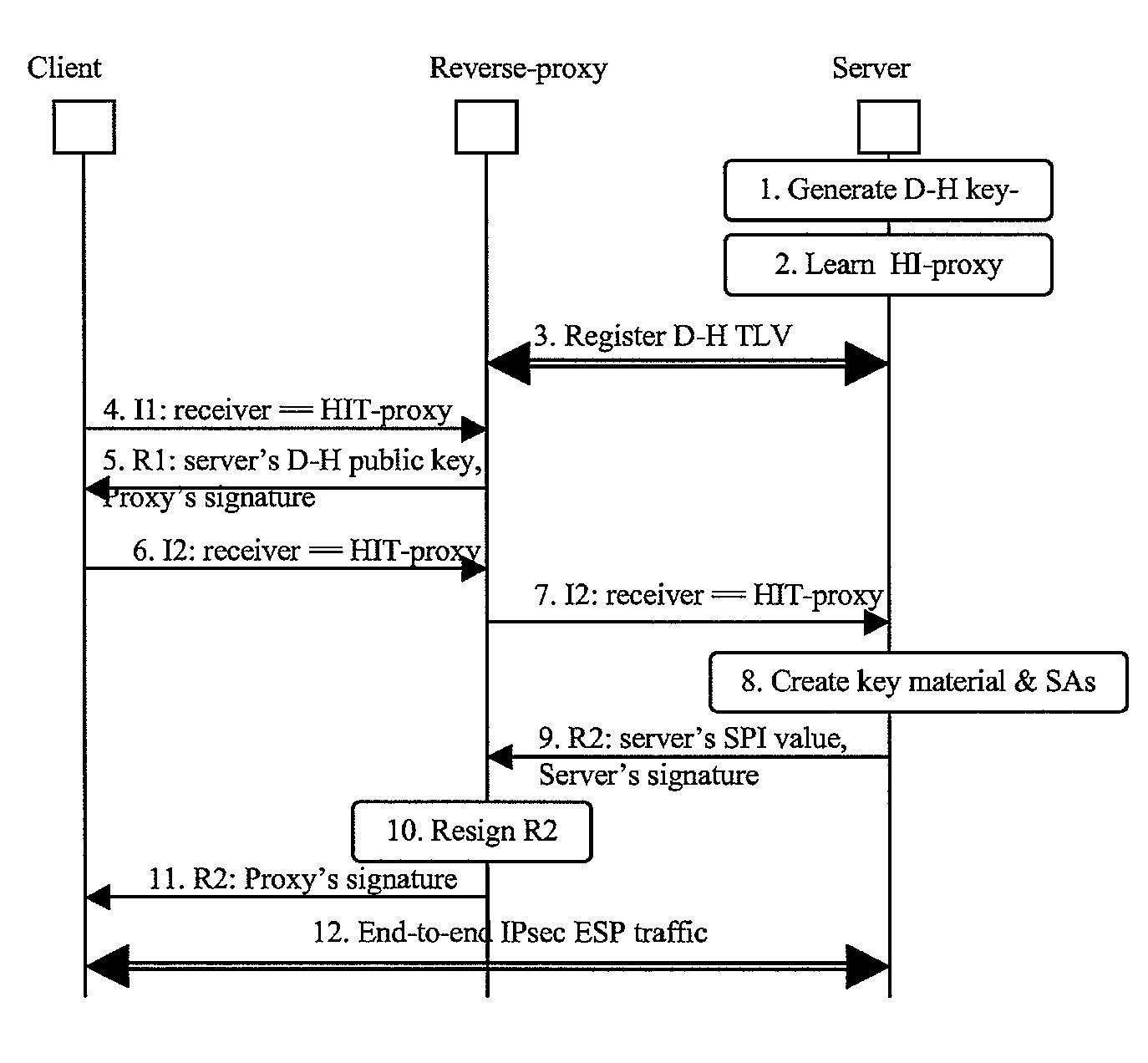
[0046]The following is an outline of a procedure for using HIP in the context of a web farm as illustrated in FIG. 4.

[0047]During an initialization phase, when a new web server is setup in the server farm of the private network, the new server generates its own public and private keys. Thus it gets its own Host Identity. It needs also Diffie-Hellman key material that will be used later to generate a shared secret with a peer node during the HIP Base Exchange. The new server generates the private part (D-H-private) and the public part (D-H-public). The web server registers to the server farm's trusted reverse-proxy and sends the D-H-public value to the reverse-proxy. The reverse-proxy generates an R1 packet, containing the D-H-public value of the server, and signs it with its own HI private key. The reverse-proxy thus maintains multiple R1 packets, (at least) one for each of the server nodes in the server farm. This situation is illustrated in FIG. 5.

[0048]When a client outside of th...


PUM


Abstract

A method of establishing a Host Identity Protocol session between first and second Host Identity Protocol enabled hosts, where at least said second host is located behind a reverse-proxy. The method comprises providing the reverse-proxy with Diffie-Hellman public keying material of the second host, sending said Diffie-Hellman public keying material from the reverse-proxy to the first host as part of the Host Identity Protocol base exchange procedure, this material being bound to the Host Identity of the reverse-proxy for the purpose of the Host Identity Protocol session, and, at the first host, using the Host Identity of the reverse-proxy as the correspondent Host Identity for the Host Identity Protocol session, and, at the second host, using the Host Identity of the reverse-proxy as the originating Host Identity for the Host Identity Protocol session.

Description

FIELD OF THE INVENTION[0001]The present invention relates to an addressing and routing mechanism for web server clusters and in particular, though not necessarily, to an addressing and routing mechanism that allows a cluster of web servers located behind a web reverse-proxy to be reachable by a client using a single Host Identity according to the Host Identity Protocol.DESCRIPTION OF THE RELATED ART[0002]When the Internet was originally devised, hosts were fixed in location and there was implicit trust between users despite the lack of real security or host identification protocols, and this situation continued even upon wider uptake and use of the technology. There was little need to consider techniques for dealing with host mobility since computers were relatively bulky and immobile.[0003]With the revolution in telecommunications and computer industry in the early 1990's, smaller communication equipment and computers became more widely available and the invention of the World Wide...

Claims


Application Information

Patent Timeline
Patent Type & Authority Patents(United States)
IPC IPC(8): H04L29/06H04L9/32
CPCH04L29/12028H04L61/103H04L63/06H04L67/1008H04L67/1002H04L67/1001
Inventor YLITALO, JUKKAJOKELA, PETRIMELEN, JANVUOPIONPERA, RAIMO
Owner TELEFON AB LM ERICSSON (PUBL)
Why Eureka
Try Eureka