Rotational operating table

a technology of operating table and rotating handle, which is applied in the direction of tables, wheelchairs/patient conveyances, transportation and packaging, etc., to achieve the effect of safe and quick turning, minimal human effort, and minimizing the chance of the table overturning

Inactive Publication Date: 2011-10-25
GILBERT JAN +4
View PDF52 Cites 33 Cited by
  • Summary
  • Abstract
  • Description
  • Claims
  • Application Information

AI Technical Summary

Benefits of technology

[0010]In the present invention, an operating table comprises a first bed platform and a second bed platform. The first and second platforms are rotated to aid in positioning a patient from a first position on one of the platforms to a second position on the other of the platforms.
[0011]The present invention provides significant advantages over the prior art. The rotation of the first and second bed platforms allows a patient to be safely and quickly turned with a minimum amount of human effort, despite the weight of a patient. The patient's weight may be maintained above the base of the table throughout the turning procedure, minimizing the chance that the table could overturn. The operating table can save significant money over time because of the considerable reduction in wasted time of operating room personnel, reduction of staff needed for turning patients, and lower liability insurance in the operating room. Further, the safety of the patient during the turn in considerably increased.

Problems solved by technology

The operating table can save significant money over time because of the considerable reduction in wasted time of operating room personnel, reduction of staff needed for turning patients, and lower liability insurance in the operating room.

Method used


Image

  • Rotational operating table
  • Rotational operating table
  • Rotational operating table

Examples


first embodiment

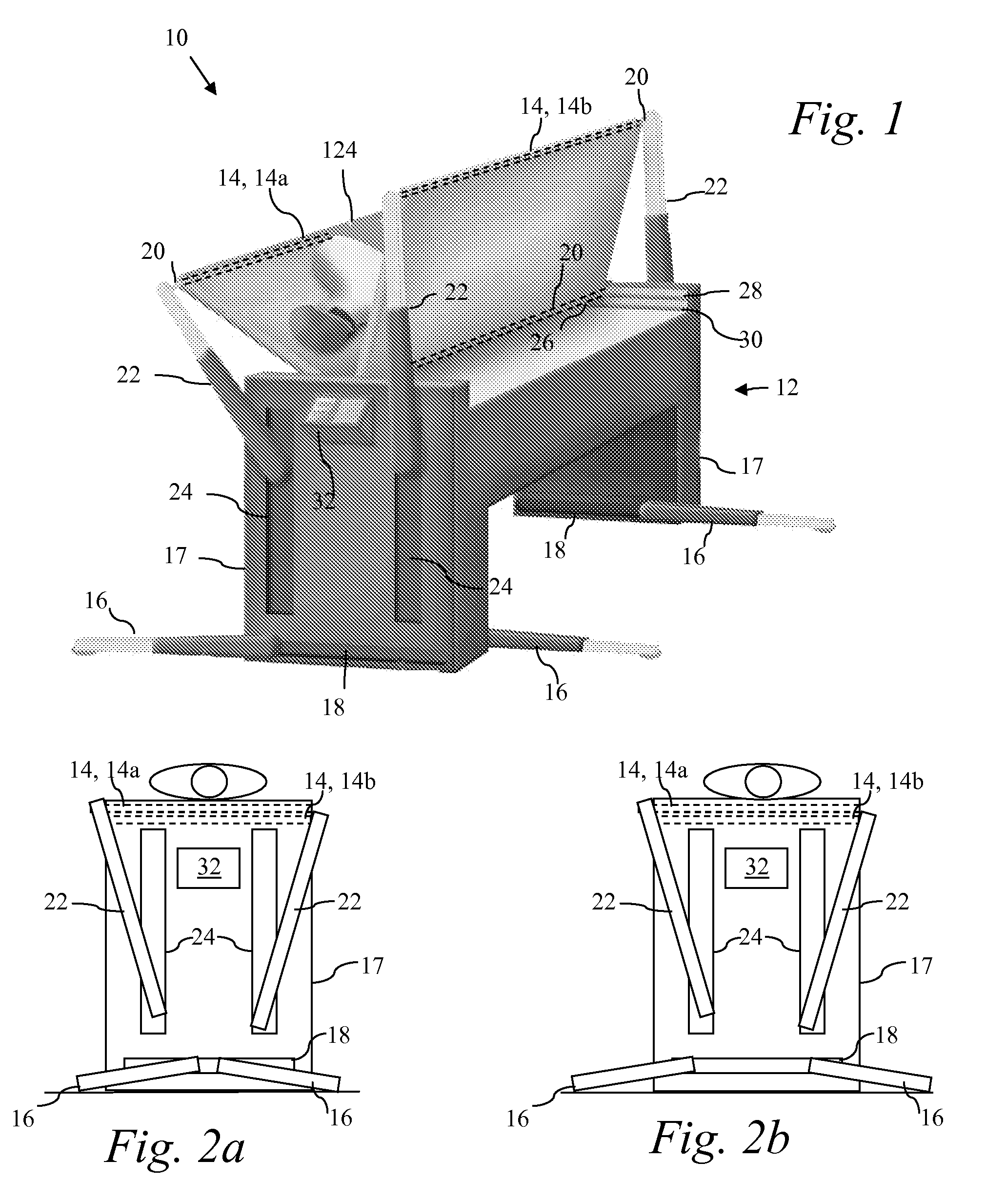
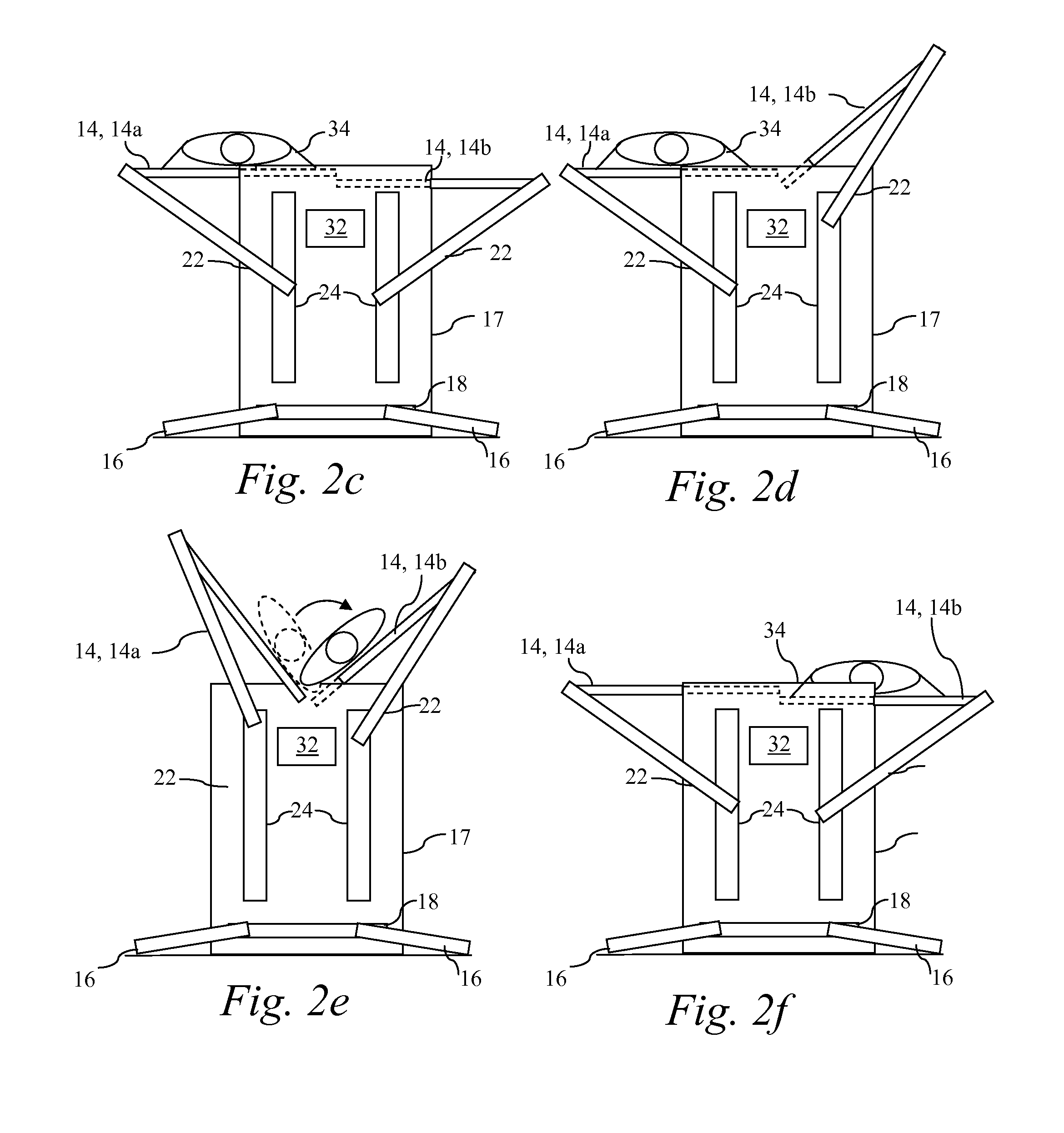
[0022]FIG. 1 illustrates an operating room table 10. A table base 12 provides a sturdy hollow housing for containing most of the moving parts and to support moving bed platforms 14 (individually referenced as 14a and 14b). The bed platforms (or “table tops”) 14 are preferably radiolucent compatible, fabricated out of a strong lightweight material, such as graphite or similar non-metallic material. At the bottom of table 10, four mechanical telescoping legs 16 are capable of moving from a normal position to an extended position, in order to provide additional stability during a transfer. Each leg 16 is connected to a motor on the inside of the table end casing 17. The end of each leg 16 is coupled to a track 18. At the connecting point, each leg 16 can rotate to allow firm placement against the floor and to allow the extensions to move in and out.

[0023]Bed platforms 14 are pivotably attached to rods 20 (for example, 0.5 inch steel rods) positioned through the length of the outside an...

second embodiment

[0030]an operating table is shown in FIG. 3, with its operation described platform in FIGS. 4a-i. The operating table 40 uses two separate, but commonly controlled, mechanisms to flip the patient. The first mechanism includes two (or more) lever arms 42 which attach to the bed platforms 44 to provide movement of the bed platform(s) 44 in a horizontal plane. The second mechanism is the array of bed platform jacks 46. The bed platform jacks 46 provide vertical movement to the bed platforms 44 during the flipping and also provide vertical positioning of the patient under normal use of the operating table 40.

[0031]Each lever arm 42 includes a TLT (table-lock-turn) wheel 48 comprising two gears 50 and a carriage 52. The two gears 50 ride on respective tracks. The carriage 52 is located between the two gears 50 of each lever arm 42. The carriage 52 can freely rotate. A motor 54 at the bottom of the lever arm 42 provides rotational motion to the lever arm 42 to position the carriage 52 at ...

third embodiment

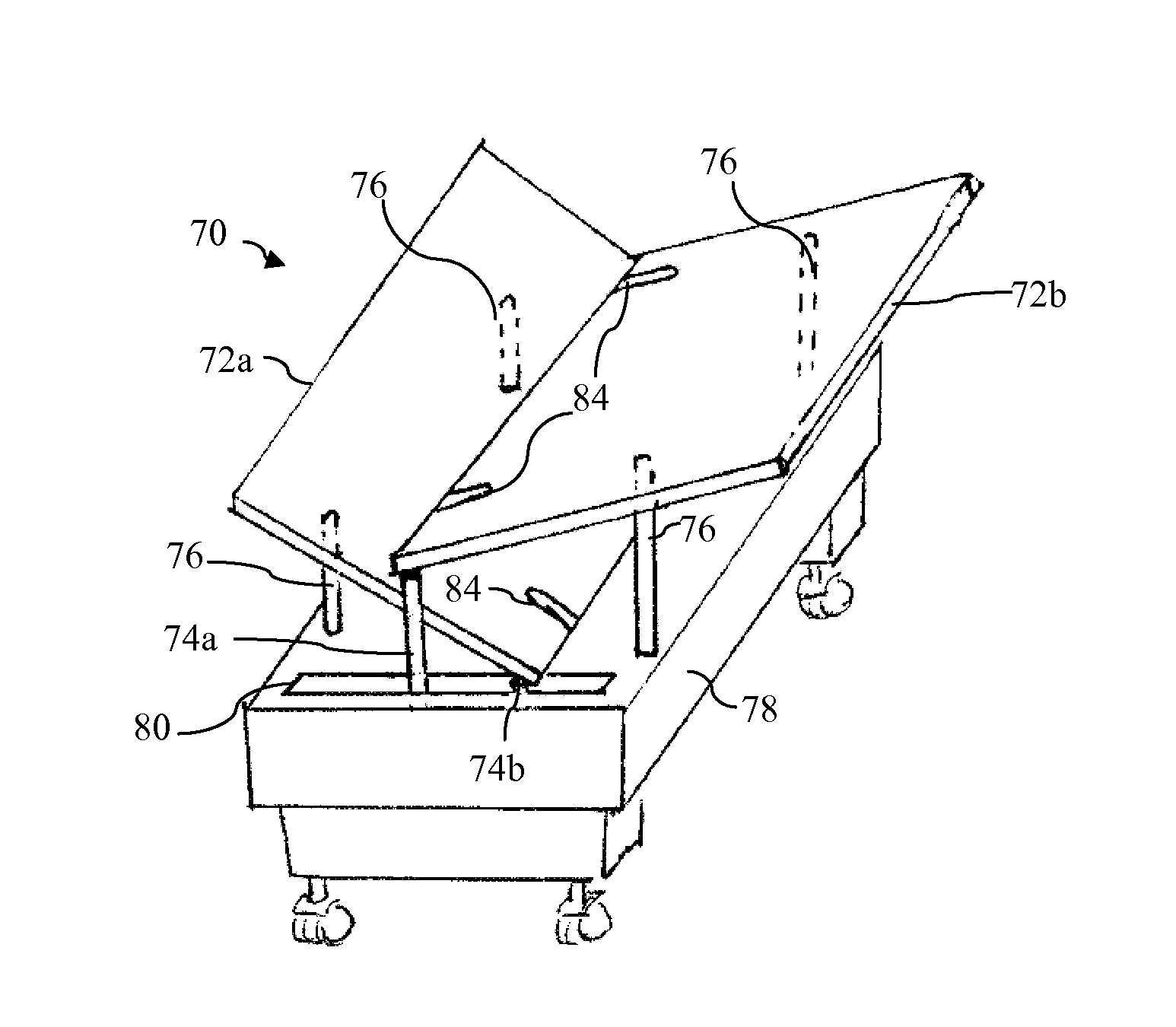
[0043]FIG. 5a illustrates a perspective view of a rotation operating table 70. Operating table 70 has first and second bed platforms 72 (individually referenced as bed platforms 72a and 72b), which are rotated by arms 74 and jacks 76 disposed in housing 78. Two pairs of arms 74 (located at each end of the table housing 78 through opening 80) include an outside arm 74a (positioned closer to the front or back of the table 70) and an inside arm 74b (positioned closer to the center of the table 70). The arms 74 are shown in greater detail in FIG. 5b. The arms 74 move both vertically and laterally; the arms can pass one another without touching; hence each arm can traverse the opening 80 from end to end. Arms 74 couple with brackets 82 (see FIG. 5b) located near the corner of the beds 72. Each arm 74a-b can attach to either bed platform 72a or 72b.

[0044]Jacks 76 move vertically up and down and the bed platforms 72 slide on the tops of the jacks 76 (the top of the jack may include a rota...


PUM


Abstract

An operating table has first bed platforms, each which can rotate. In an operating configuration, the patient lies on one of the bed platforms in a prone or supine position with the bed platform centered over the base. When the patient needs to be turned, the other table extends outwardly, and both tables are rotated to position the patient for turning. Once the patient is turned, the table on which the patient lies is returned to its operating position over the base and the other table is returned to its storage position.

Description

CROSS-REFERENCE TO RELATED APPLICATIONS[0001]This application claims the benefit of the filing date of copending provisional applications U.S. Ser. No. 60 / 756,432, filed Jan. 5, 2006, entitled “ROTATIONAL OPERATING TABLE”, U.S. Ser. No. 60 / 774,940, filed Feb. 17, 2006, entitled “ROTATIONAL OPERATING TABLE” and U.S. Ser. No. 60 / 807,544, filed Jul. 17, 2006, entitled “ROTATIONAL OPERATING TABLE”, which are incorporated by reference herein.STATEMENT OF FEDERALLY SPONSORED RESEARCH OR DEVELOPMENT[0002]Not ApplicableBACKGROUND OF THE INVENTION[0003]1. Technical Field[0004]This invention relates in general to hospital equipment and, more particularly, to an operating table.[0005]2. Description of the Related Art[0006]Throughout a surgical procedure, there may be a need to switch a patient between supine and prone positions (and vice versa) on an operating table. The rotation of the patient wastes a considerable amount of time on behalf of the surgeon and his team, as well as medical facil...

Claims


Application Information

Patent Timeline
Patent Type & Authority Patents(United States)
IPC IPC(8): A47B7/00
CPCA61G13/04A61G7/001
Inventor GILBERT, JANSTIDD, RAYMOND E.HOUGHTON-WARD, EDWARDMCCROCKLIN, JASONLING, JEREMY JOHN
Owner GILBERT JAN
Why Eureka
Try Eureka