Engine assembly for aircraft comprising an engine as well as a device for locking said engine

a technology for aircraft and engine parts, which is applied in the direction of machines/engines, mechanical equipment, transportation and packaging, etc., can solve the problems of affecting the life and affecting the performance of the engine, and inevitably encountering strong friction, so as to reduce the bending and reduce the friction. , the effect of limiting the yield loss

Inactive Publication Date: 2011-10-25
AIRBUS OPERATIONS (SAS)
View PDF11 Cites 18 Cited by
  • Summary
  • Abstract
  • Description
  • Claims
  • Application Information

AI Technical Summary

Benefits of technology

[0018]As a result, this special arrangement of the engine attachments leads to considerably reduced bending encountered at the central case, whether this bending is due to thrust loads generated by the engine, or to wind gusts which may be encountered during the various flight phases of the aircraft.
[0019]Therefore, the above-mentioned reduction in bending generates a significant decrease in friction between the rotating compressor and turbine blades and the central engine case, and hence largely limits yield losses due to early wear of these blades.
[0020]By way of indication, it is noted that by making provision for one engine attachment on the fan case and one engine attachment on the forward part of the central engine case, this fact offers the possibility to space them well away from each other. The advantage of such spacing is the ability to simplify the design of these engine attachments, owing to the fact that the loads they are to transfer, associated with a moment along a given axis, are naturally weakened compared with those found in conventional prior art solutions, in which the engine attachments located solely on the central case are not able to be spaced so far apart.
[0021]Finally, it is indicated that the engine attachments and the engine mount can advantageously be positioned away from the hot part of the engine, which involves a significant reduction in the thermal effects which may be applied to these elements.
[0024]Preferably, the second engine attachment is fixed to a portion of the front part of the central case which carries the fixed blades connecting this central case to said fan case. In this case, it is effectively the entire part of the engine located to the aft of the fan case which is advantageously free of any link with the mounting means, and which is therefore able to move freely without undergoing any longitudinal bending.
[0031]Finally, it is indicated that advantageously the mounting system is an isostatic system, which largely facilitates its design.

Problems solved by technology

In this respect, it is also noted that under aircraft cruise conditions the thrust loads are the sole cause of longitudinal bending of the engine.
In a first case, in which no particular precaution has been taken regarding the observed bending, strong friction is inevitably encountered firstly between the rotating fan blades and the fan case, and secondly between the rotating compressor and turbine blades and the central engine case.
The main consequence of such friction is early wear of the engine, which is evidently detrimental to its lifetime and to its level of performance.
It has been observed, however, that the mounting means in the prior art do not allow fully satisfactory limitation of engine longitudinal bending which results from transverse axis torque related to thrust loads, in particular during cruise phases of the aircraft.

Method used


Image

  • Engine assembly for aircraft comprising an engine as well as a device for locking said engine
  • Engine assembly for aircraft comprising an engine as well as a device for locking said engine
  • Engine assembly for aircraft comprising an engine as well as a device for locking said engine

Examples


Embodiment Construction

[0046]In the figures showing different preferred embodiments of the present invention, those elements carrying the same references correspond to identical or similar elements.

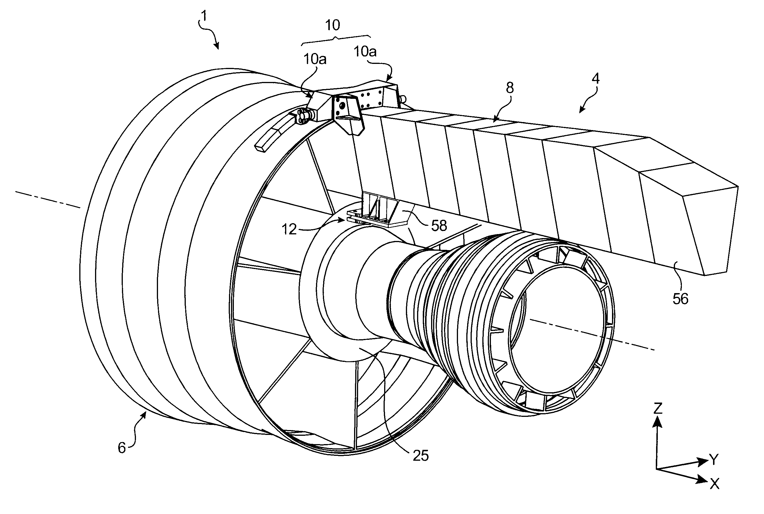
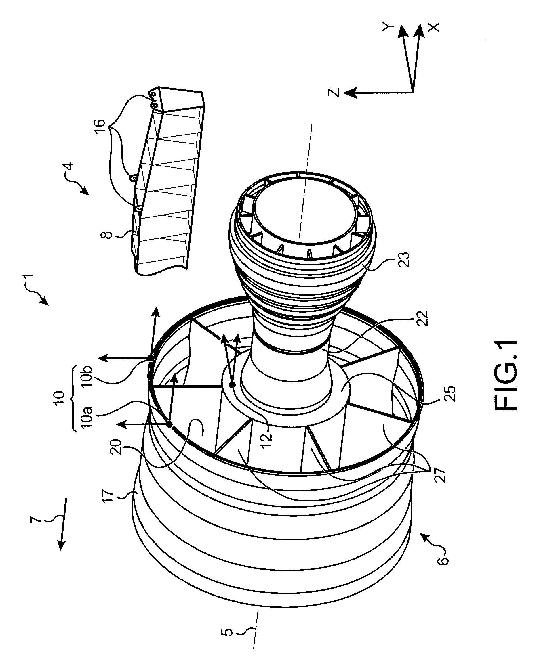
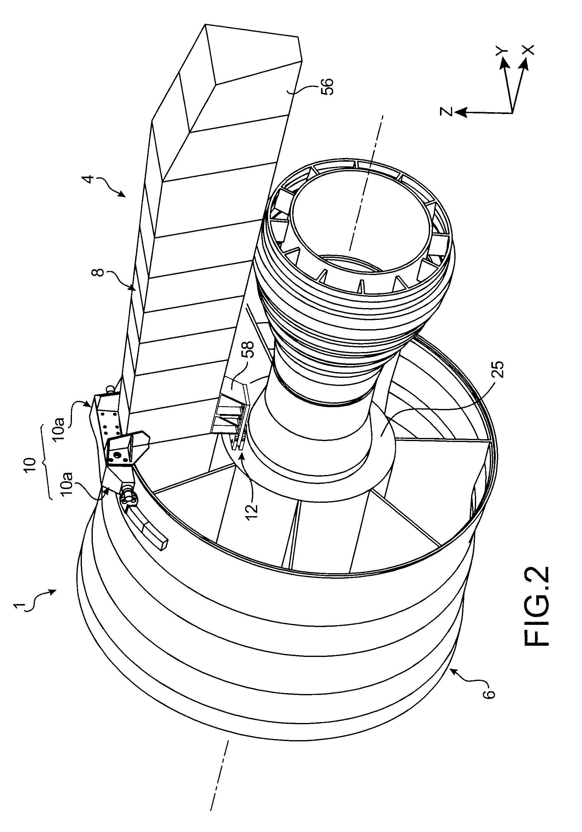
[0047]With reference first to FIG. 1, an engine assembly 1 can be seen intended to be suspended below a wing (not shown) of this aircraft, this assembly 1 being in the form of a first preferred embodiment of the present invention comprising a mount device 4 and an engine 6 such as a turbojet engine mounted below this device 4.

[0048]Globally, the mount device 4 comprises a rigid structure 8 carrying means to mount the engine 6, these mounting means consisting of two engine attachments 10, 12.

[0049]By way of indication, it is noted that assembly 1 is intended to be surrounded by a nacelle (not shown), and the mount device 4 comprises another series of attachments 16 used to suspend this assembly 1 below the aircraft wing.

[0050]In the remainder of the description, by convention, X is used to designate the longitud...


PUM


Abstract

An aircraft engine assembly including an engine and a mount device for the engine. The mount device can be positioned between a wing of the aircraft and the engine, and includes a rigid structure and a mechanism to mount the engine on the rigid structure, the mounting mechanism including a first attachment and a second attachment. The first attachment includes two side semi-attachments each fixed to a fan case of the engine, and the second attachment is fixed onto a forward part of a central case of the engine.

Description

TECHNICAL AREA[0001]The present invention generally pertains to the area of pylons for the securing of aircraft engines, intended to be positioned between an aircraft wing and an engine, and more particularly pertains to an engine assembly comprising said pylon device.[0002]The invention can be used on any type of aircraft equipped with turbojet engines or turboprop engines, or further with any type of engine.[0003]This type of securing pylon also called <<EMS>> for Engine Mounting Structure, can be used to suspend a turbojet engine below an aircraft wing or to mount this turbojet engine above this same wing.STATE OF THE PRIOR ART[0004]An aircraft engine mounting device is designed to form the connecting interface between an engine and the aircraft wing. It permits the loads generated by its associated engine to be transmitted to the airframe, and also provides a path for fuel lines, electricity, hydraulics and air between the engine and the aircraft.[0005]To ensure the ...

Claims


Application Information

Patent Timeline
Patent Type & Authority Patents(United States)
IPC IPC(8): F02K3/04
CPCB64D27/26B64D2027/264
Inventor DIOCHON, LIONELMASTROBERTI, RAFFAELLAPETRISSANS, ISABELLE
Owner AIRBUS OPERATIONS (SAS)
Why Eureka
Try Eureka