Wind turbine blade with prefabricated leading edge segments

a technology of leading edge segments and wind turbine blades, which is applied in the manufacture of final products, vessel construction, marine propulsion, etc., can solve the problems of difficult control of the bonding of shell components at the leading edge, high risk of erosion of the edge of the turbine blade, and extensive rework of the blad

Active Publication Date: 2011-10-25
LM WIND POWER US TECH APS
View PDF20 Cites 35 Cited by
  • Summary
  • Abstract
  • Description
  • Claims
  • Application Information

AI Technical Summary

Benefits of technology

[0009]It should be readily appreciated, that the other attributes and characteristics of the various embodiments described herein relate to the individual components of the kit embodiments as well.

Problems solved by technology

The bonding of the shell components at the leading edge is difficult to control.
Overbite or underbite between the shell components can occur, often causing extensive rework of the blade.
In addition, the leading edge of the turbine blade is highly susceptible to erosion and weathering, and can be damaged during transportation and erection of the wind turbine.
These conditions lead to costly on-site repairs.

Method used


Image

  • Wind turbine blade with prefabricated leading edge segments
  • Wind turbine blade with prefabricated leading edge segments
  • Wind turbine blade with prefabricated leading edge segments

Examples


Embodiment Construction

[0020]Reference now will be made in detail to embodiments of the invention, one or more examples of which are illustrated in the drawings. Each example is provided by way of explanation of the invention, not limitation of the invention. In fact, it will be apparent to those skilled in the art that various modifications and variations can be made in the present invention without departing from the scope or spirit of the invention. For instance, features illustrated or described as part of one embodiment, can be used with another embodiment to yield a still further embodiment. Thus, it is intended that the present invention covers such modifications and variations as come within the scope of the appended claims and their equivalents.

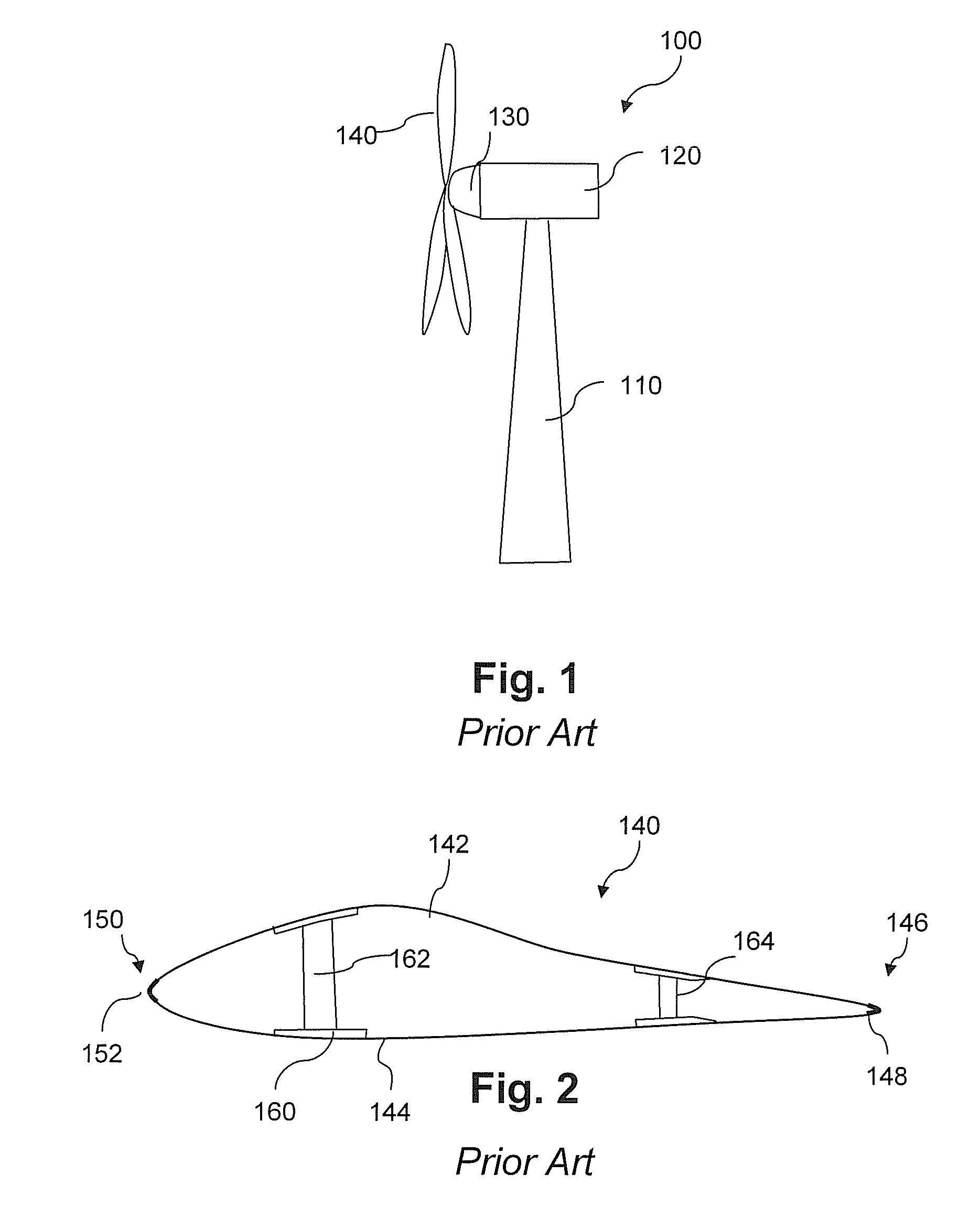
[0021]FIG. 1 is a schematic view of a conventional wind turbine 100. The wind turbine 100 includes a tower 110 with a machine nacelle 120 mounted at the top of the tower. A hub 130 having any number of rotor blades 140 is mounted to a lateral end of the ma...


PUM


Abstract

A wind turbine rotor blade includes first and second shell components joined together at a trailing edge of the blade. Each shell component includes a forward edge. At least one leading edge segment is joined to the shell components and aligned along a longitudinal length of the blade. The leading edge segment has an open-ended cross-sectional profile defined by an arcuate skin having first and second longitudinal edges and first and second end faces. The longitudinal edges of the leading edge segment are joined to the forward edge of the first shell component at a first bond line, and joined to the forward edge of the second shell component at a second bond line. The leading edge of the blade between the first and second bond lines is a continuous unbroken surface between the bond lines.

Description

FIELD OF THE INVENTION[0001]The present invention relates generally to wind turbine rotor blades, and more particularly to a wind turbine rotor blade having one or more prefabricated leading edge componentsBACKGROUND[0002]Wind power is considered one of the cleanest, most environmentally friendly energy sources presently available, and wind turbines have gained increased attention in this regard. A modern wind turbine typically includes a tower, generator, gearbox, nacelle, and one more rotor blades. The rotor blades capture kinetic energy from wind using known foil principles, and transmit the kinetic energy through rotational energy to turn a shaft coupling the rotor blades to a gearbox, or if a gearbox is not used, directly to the generator. The generator then converts the mechanical energy to electrical energy that may be deployed to a utility grid.[0003]The construction of a modern wind turbine rotor blade generally includes upper and lower shell components bonded at a leading ...

Claims


Application Information

Patent Timeline
Patent Type & Authority Patents(United States)
IPC IPC(8): F01D5/18
CPCF03D1/0675F03D11/0033F05B2230/50F05B2230/60Y02P70/523Y02E10/722Y02E10/721F03D80/30Y02E10/72Y02P70/50
Inventor KYRIAKIDES, STEVEN ALAN
Owner LM WIND POWER US TECH APS
Why Eureka
Try Eureka