Power receptacle for portable electronic device

a technology for electronic devices and power receptacles, which is applied in the direction of coupling contact members, coupling device connections, electric discharge lamps, etc., can solve the problems of security and reliability of power receptacles, increase of contact impedance of terminals, and structure of power receptacles, so as to achieve low contact impedance and good reliability

Inactive Publication Date: 2011-10-25
COMPAL ELECTRONICS INC
View PDF1 Cites 16 Cited by
  • Summary
  • Abstract
  • Description
  • Claims
  • Application Information

AI Technical Summary

Benefits of technology

[0009]The invention is directed to a power receptacle for a portable electronic device, which may have a good reliability by maintaining a low contact impedance between terminals of the power receptacle and a power plug.
[0016]According to the above descriptions, in the power receptacle for the portable electronic device, based on a relative configuration of the anode terminal and the cathode terminal in the insulating housing, during a process of plugging the power plug in the receiving cavity of the insulating housing, the cathode terminal first contacts the tubular terminal, and then the anode terminal contacts the clamping terminal. In this way, a contact impedance between the terminals can be maintained, so as to avoid a risk of high temperature caused by a high impedance due to a prior contact of the anode terminals. Therefore, the power receptacle may have a good reliability and security.

Problems solved by technology

Although the power receptacles are continuously developed by various manufactures, there are still problems in security and reliability of the power receptacle.
However, during the above process, if the power plug or the power receptacle has a poor structure design or the power plug is only plugged into the power receptacle by a half, i.e. only the anode terminals of the power plug and the power receptacle are connected, a contact impedance of the terminals is increased due to such instable connection state, so that once such abnormal power supplying state lasts for a long time, a structure of the power receptacle or the power plug can be damaged due to overheating, or even the whole device is burnout.

Method used


Image

  • Power receptacle for portable electronic device
  • Power receptacle for portable electronic device
  • Power receptacle for portable electronic device

Examples


Embodiment Construction

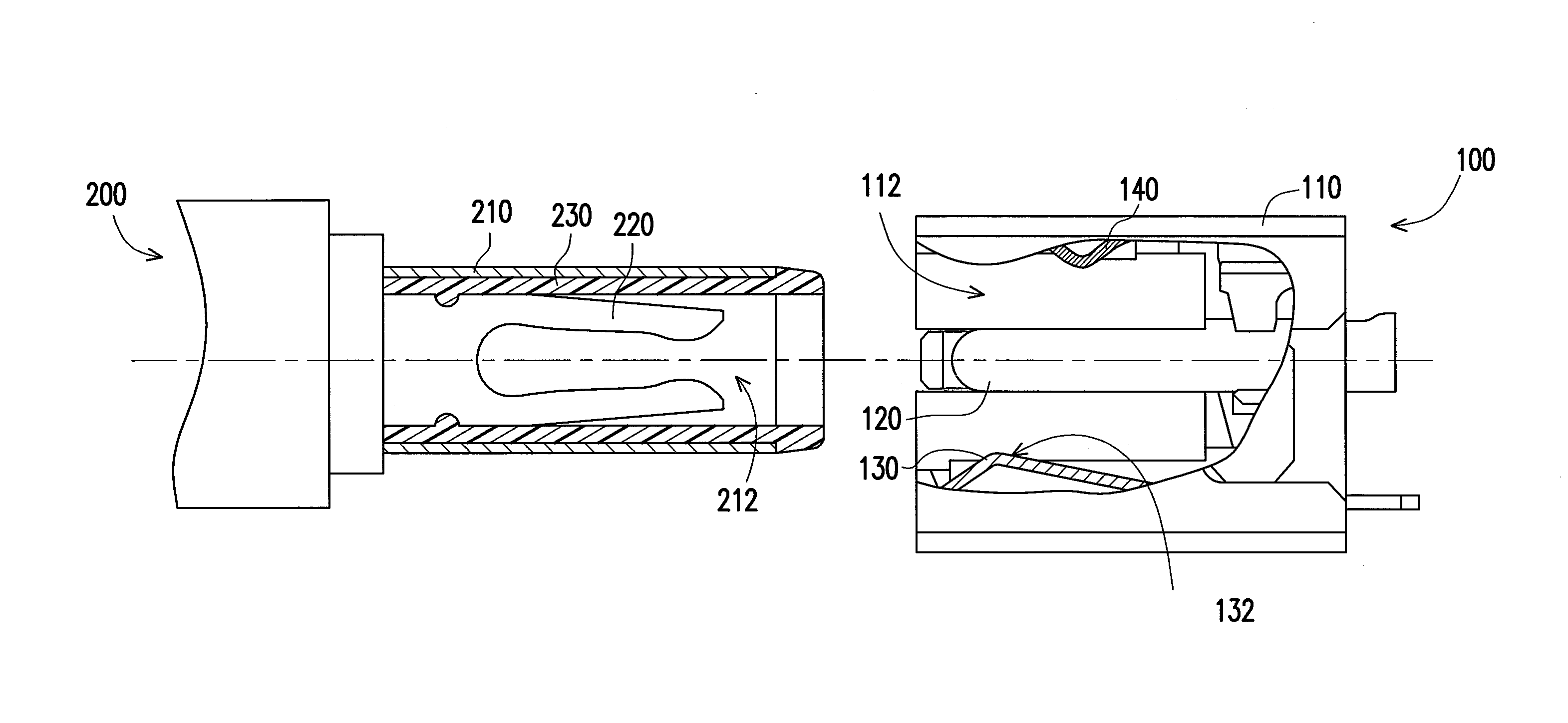
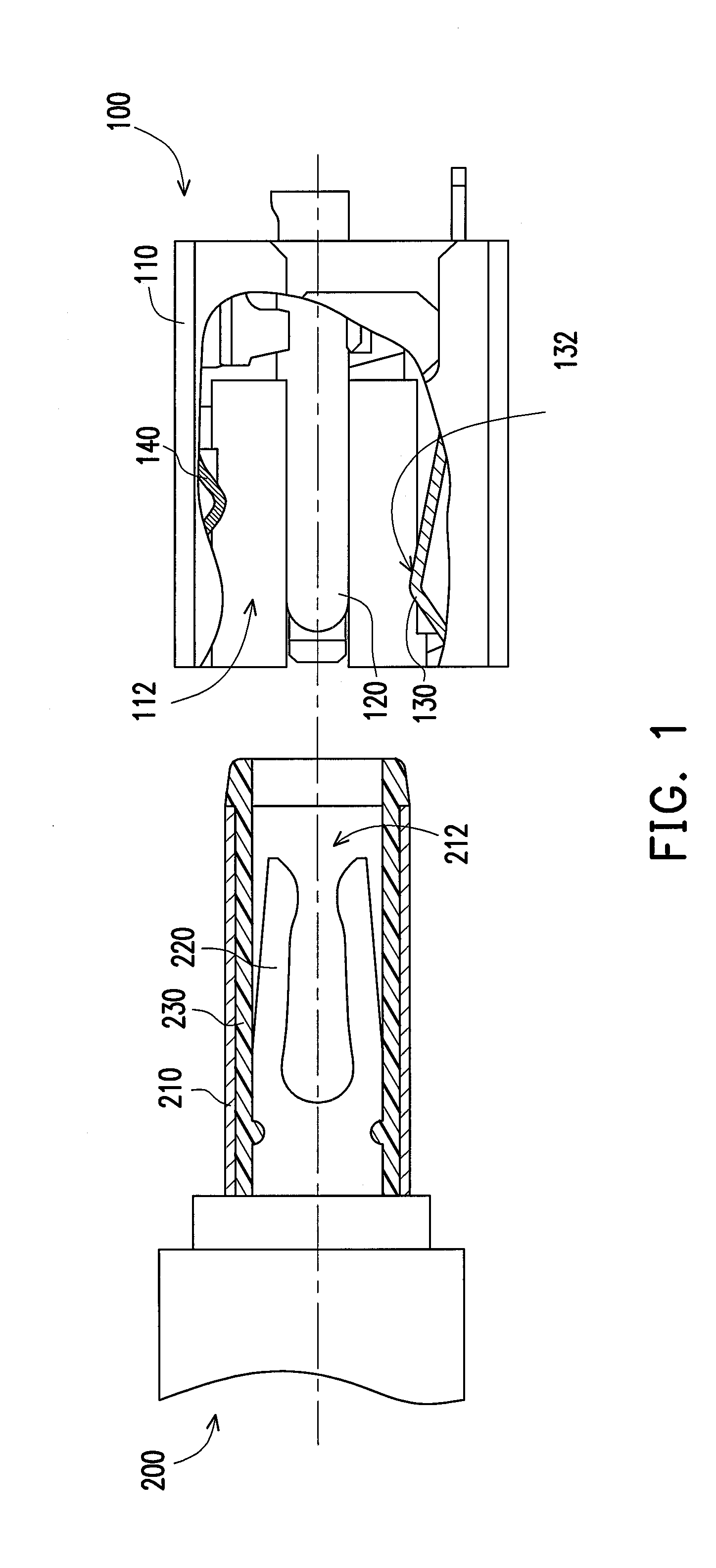
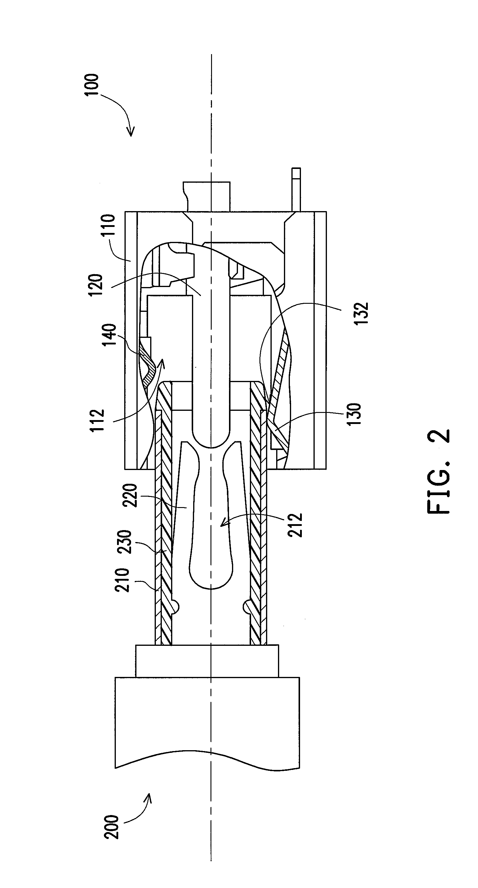
[0020]FIGS. 1-3 are diagrams illustrating a process of plugging a conventional power plug in a power receptacle according to an embodiment of the invention. Referring to FIGS. 1-3, in the present embodiment, the power receptacle 100 is adapted to be applied to a portable electronic device (not shown) for connecting a power plug 200. The power plug 200 has a tubular terminal 210, a clamping terminal 220 disposed in the tubular terminal 210 and a tubular insulator 230 disposed between the tubular terminal 210 and the clamping terminal 220 for insulation.

[0021]The power receptacle 100 includes an insulating housing 110, an anode terminal 120, and a cathode terminal 130. The insulating housing 110 has a first receiving cavity 112, and the power plug 200 is suitable for being plugged in the first receiving cavity 112. The anode terminal 120 is disposed in the insulating housing 110 and is located at a central part of the first receiving cavity 112. The cathode terminal 130 is disposed in...


PUM


Abstract

A power receptacle for a portable electronic device suitable for connecting a power plug is provided. The power plug has a tubular terminal and a clamping terminal in the tubular terminal. The power receptacle includes an insulating housing, an anode terminal, and a cathode terminal. The insulating housing has a receiving cavity, and the power plug is suitable for being plug in the receiving cavity. The anode terminal disposed in the insulating housing is located at the central part of the receiving cavity. The cathode terminal disposed in the insulating housing is located at a side of the receiving cavity. During a process of plugging the power plug into the receiving cavity, the tubular terminal contacts the cathode terminal, and then the clamping terminal contacts the anode terminal, so that the power plug is electrically connected to the power receptacle.

Description

CROSS-REFERENCE TO RELATED APPLICATION[0001]This application claims the priority benefit of U.S.A. provisional application Ser. No. 61 / 251,746 filed on Oct. 15, 2009, and application Ser. No. 61 / 262,560 filed on Nov. 19, 2009. The entirety of the above-mentioned patent application is hereby incorporated by reference herein and made a part of specification.BACKGROUND[0002]1. Field of the Invention[0003]The invention relates to a power receptacle. More particularly, the invention relates to a power receptacle for a portable electronic device.[0004]2. Description of Related Art[0005]A direct current (DC) power receptacle is a most important connection port of a notebook computer, and power supplying and battery charging all rely on the DC power receptacle. Although the power receptacles are continuously developed by various manufactures, there are still problems in security and reliability of the power receptacle.[0006]According to an existing technology, during a process of plugging a...

Claims


Application Information

Patent Timeline
Patent Type & Authority Patents(United States)
CPCH01R13/04H01R13/112H01R2201/06
Inventor HSIEH, SHENG-MING
Owner COMPAL ELECTRONICS INC
Why Eureka
Try Eureka