Multi-phase voltage regulator

a voltage regulator and multi-phase technology, applied in the direction of electric variable regulation, power conversion systems, instruments, etc., can solve the problems of reducing the number of pins required by the controller reducing the number of pins required to read the output signal, and reducing the use of external components. the effect of reducing the number of pins

Active Publication Date: 2011-10-25
STMICROELECTRONICS SRL
View PDF12 Cites 16 Cited by
  • Summary
  • Abstract
  • Description
  • Claims
  • Application Information

AI Technical Summary

Benefits of technology

[0028]In view of the foregoing background, an object of the present invention is to provide a voltage regulator comprising a straightforward and reliable Current Sense circuit having structural and functional features so as to make the regulator particularly compact. This allows the use of external components to be minimized or reduced. This in turn also reduces the area occupied on the silicon chip where the voltage regulator is integrated, and the area occupied on the board. The number of pins required by the controller to read the output signal is also reduced.

Problems solved by technology

Nevertheless, this approach has for its known advantages the drawback of being a higher cost and for providing a reduced current conversion efficiency.
But it also provides a less precise reading that is sensitive to single element errors, and to the variations produced therefrom according to the temperature of the regulator.
However, the voltage regulator according to the provided approach, although advantageous under several aspects, has some drawbacks.
The capacitor CCS is generally of the COG type, and is particularly expensive.
This involves a regulator circuit complexity and the need for a considerable surface for the in-silicon-chip integration.
Moreover, the N R-C networks can insert some delays in output signals that could invalidate the voltage regulator reliability.
In voltage regulators that are currently available, the presence of more precise components to meet the need for more stringent specifications, poses further problems.
In particular, the use of smaller and smaller inductors with lower and lower parasitic resistances RL clashes with the presence of the parasitic resistances on the application boards because of the unavoidable resistances due to the copper tracks.
Therefore, if there were different parasitic resistances for the two phases, an error would be committed in the current measure.

Method used


Image

  • Multi-phase voltage regulator
  • Multi-phase voltage regulator
  • Multi-phase voltage regulator

Examples


Embodiment Construction

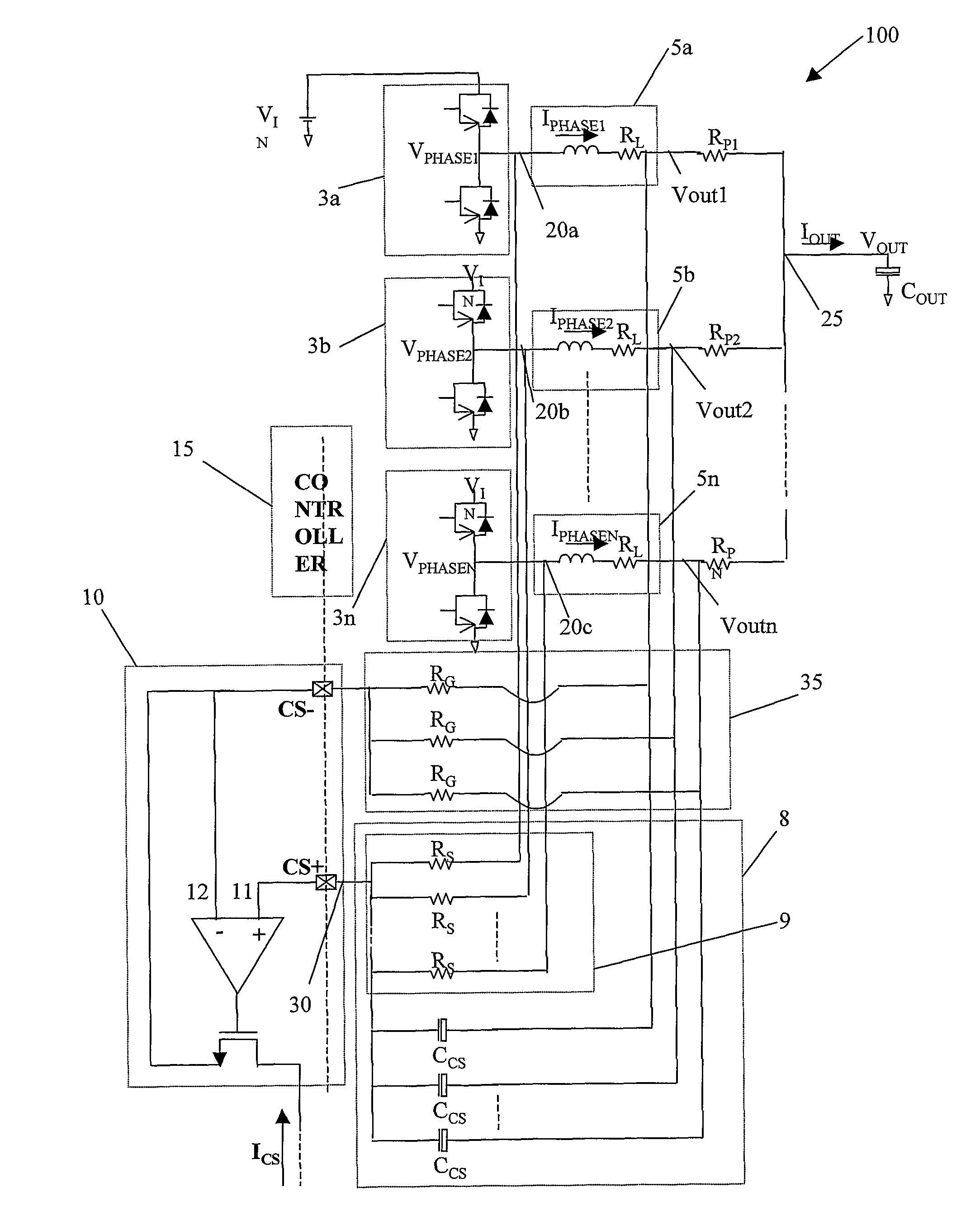
[0043]With reference to the figures, and particularly to FIG. 6, a voltage regulator 1 according the present invention is shown. The voltage regulator 1 generates an output voltage VOUT for a general load, indicated with COUT.

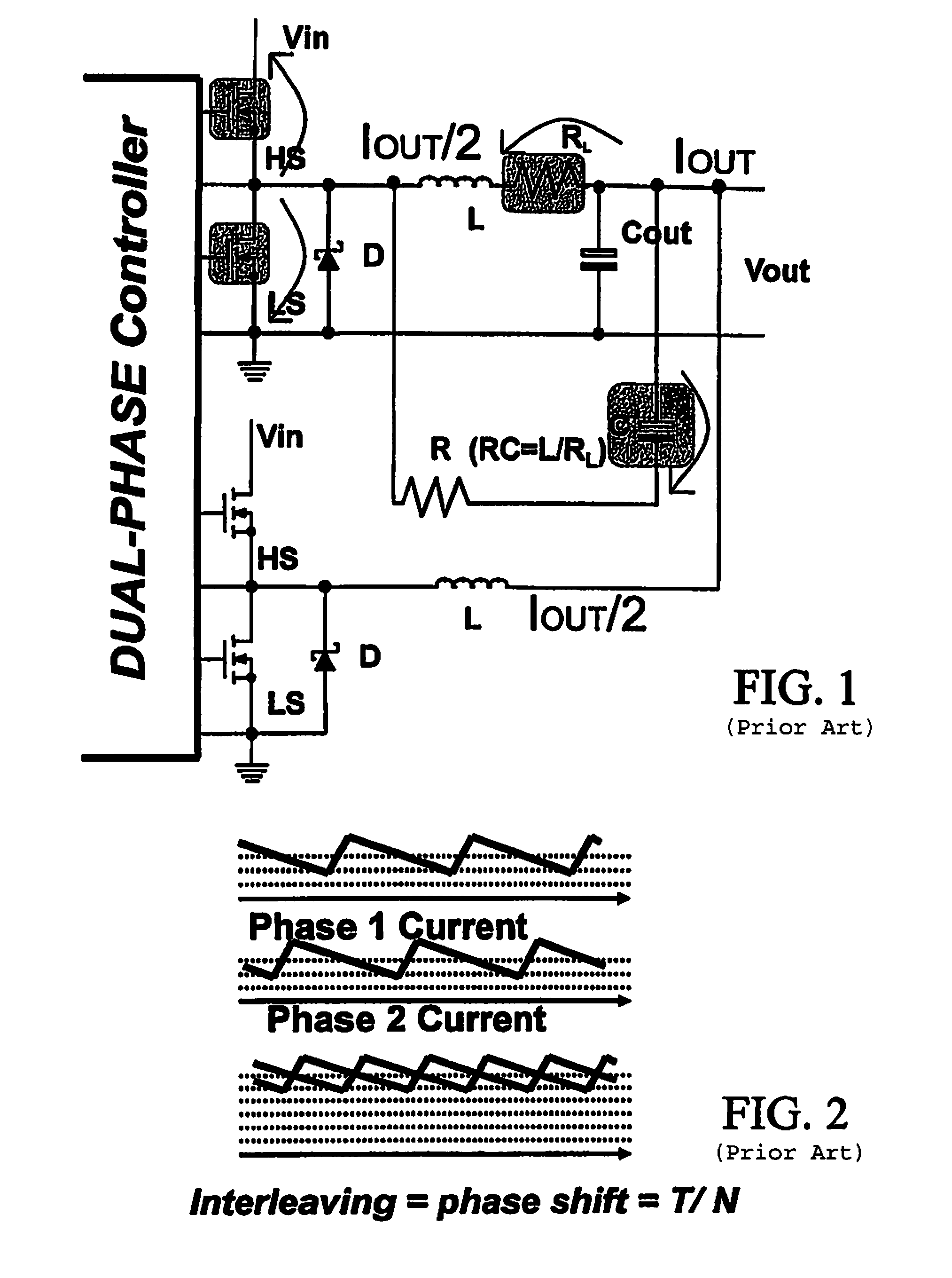
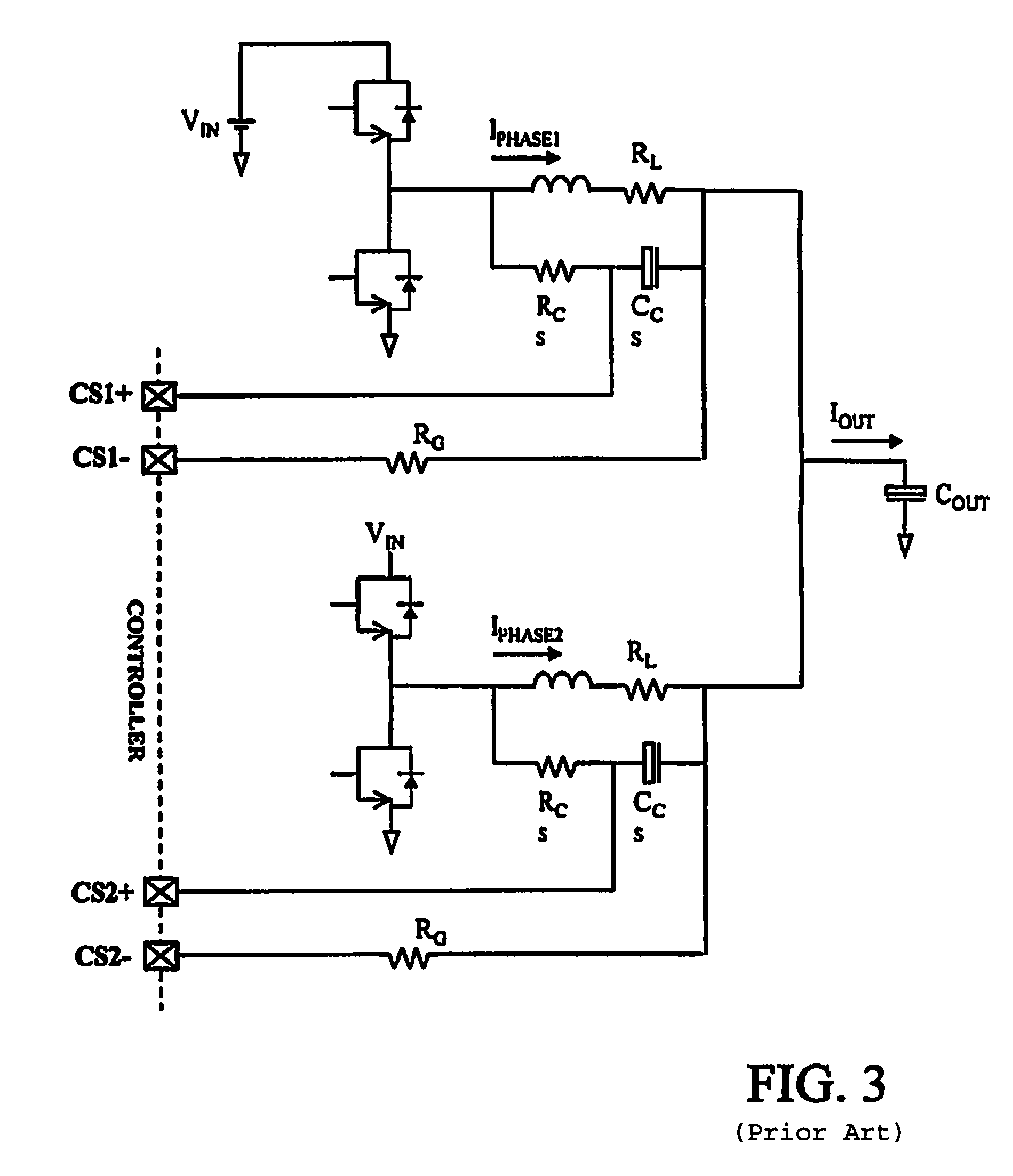
[0044]For convenience of illustration, a dual-phase voltage regulator 100 is shown in FIG. 7. The dual-phase voltage regulator 100 comprises a first switch 3a and a second switch 3b located in parallel to each other. Each switch is interposed between an input current VIN and a ground current.

[0045]For greater clarity, it is first considered that the parasitic resistances due to the board copper tracks are negligible. A more detailed description will be provided below.

[0046]The first and second switches 3a, 3b have a voltage VPHASE1, VPHASE2 at the respective output nodes 20a, 20b and respective current phases IPHASE1, IPHASE2 which, through respective inductive circuits 5a, 5b added in correspondence with an output terminal 25 generate the total current IOUT to...


PUM


Abstract

A multiphase voltage regulator provides a voltage to an output terminal. The voltage regulator includes N parallel switches providing respective current phases that are added together to generate a total current for a general load coupled to the output terminal. The voltage regulator also includes N inductive circuits. Each inductive circuit is between an output node of a respective switch and the output terminal. A sense circuit adds the voltages in each of the output nodes of the N switches. An amplifier circuit has an input receiving the added voltage, and outputs a current proportional to the total current. A controller with two pins reads the total current. The two pins are connected to the inputs of the amplifier.

Description

RELATED APPLICATION[0001]This application claims the benefit of International Application No. PCT / IT2005 / 000205 filed Apr. 12, 2005, the entire contents of which are incorporated herein by reference.FIELD OF THE INVENTION[0002]Moreover, the first input 11 and the second input 12 of the operational amplifier 10 are the only two pins CS+ and CS− used by a controller 15 to read the current IOUT. The controller 15 is schematically represented in the figure and operates on the input voltage VIN of the first and second switch 3a and 3b to keep the sum of the current phases IPHASE1, IPHASE2 and thus the total current IOUT constant.BACKGROUND OF THE INVENTION[0003]The multiphase voltage regulator is an electronic device used in several applications. For example, the multiphase voltage regulator may be used as a power supply in microprocessors for personal computers, workstations, servers, printers and other similar electronic equipment.[0004]Electronic device microprocessors are at present ...

Claims


Application Information

Patent Timeline
Patent Type & Authority Patents(United States)
IPC IPC(8): G05F1/59
CPCH02M3/1584H02M2001/0009H02M1/0009
Inventor ZAMBETTI, OSVALDO ENRICOZAFARANA, ALESSANDRO
Owner STMICROELECTRONICS SRL
Why Eureka
Try Eureka