
System and method for controlling remote sensors

a technology for remote sensors and remote sensors, applied in the field of system and method for controlling remote sensors, can solve the problems of strict export restrictions, tightly controlled export of these devices, even for commercial purposes, and large commercial business potential of these devices

Active Publication Date: 2011-10-25
HEWLETT PACKARD DEV CO LP
View PDF6 Cites 106 Cited by
  • Summary
  • Abstract
  • Description
  • Claims
  • Application Information

AI Technical Summary

Benefits of technology

The patent describes a system for controlling and monitoring position-determining sensors, such as accelerometers and gyroscopes, that are used in commercial and military applications. The system is designed to prevent unauthorized use of these sensors and to allow for limited and controlled use in various countries. The system includes a secure computing system that communicates with the sensors through wireless communication links and uses encryption technology to safeguard sensitive data. The system also includes a use control system that allows the operator to control the sensors in a desired manner. Overall, the system provides multiple layers of protection to ensure that the sensors cannot be used for any unauthorized purposes.

Problems solved by technology

Because some of these uses (for instance missile guidance, have national security issues, export of these devices, even for commercial purposes, is closely controlled.
However, the commercial business potential of these devices is greatly limited is greatly limited by governmental export restrictions.
Because the high performance characteristics of these devices could potentially be diverted to enable military applications (such as ballistic missile technology), these devices encounter strict export restrictions.

Method used


Image

  • System and method for controlling remote sensors
  • System and method for controlling remote sensors
  • System and method for controlling remote sensors

Examples


Embodiment Construction

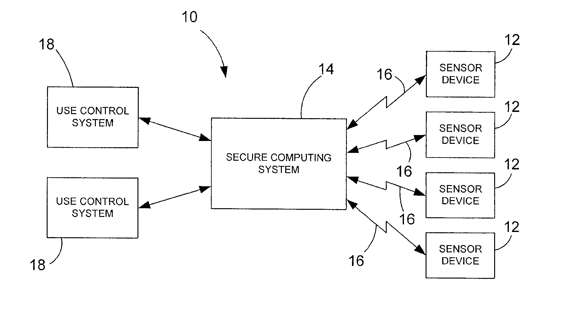
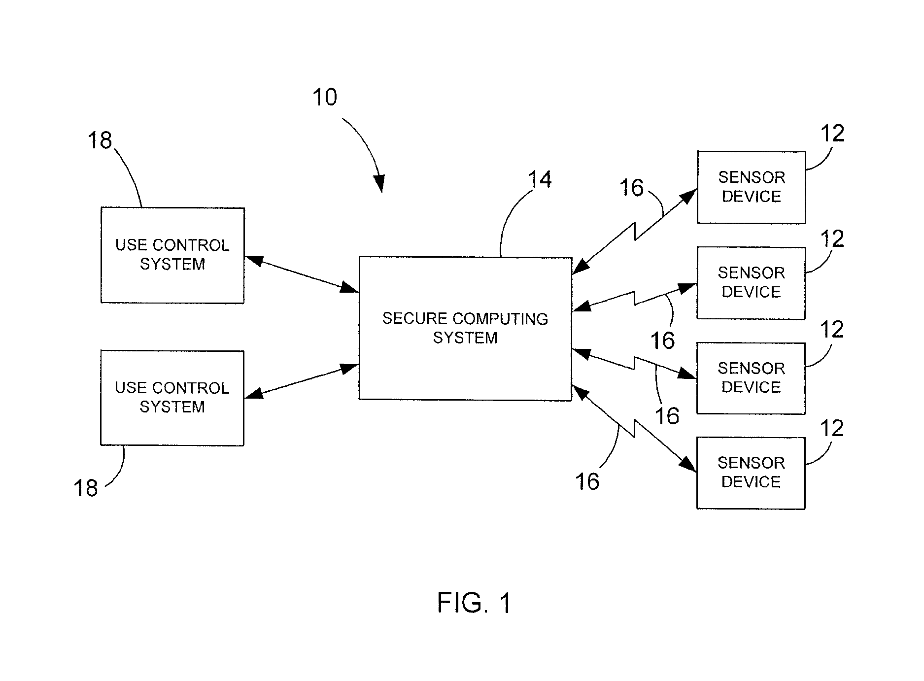
[0007]Referring to the drawings wherein identical reference numerals denote the same elements throughout the various views, FIG. 1 shows one embodiment of a sensor control system 10 for controlling a number of remote sensor devices 12 that are being used in the field by one or more commercial entities in a variety of different applications. Four such remote sensor devices 12 are shown in FIG. 1 for the sake of example, but it should be noted that the sensor control system 10 can work with any number of sensor devices. In fact, the system 10 is well suited for controlling large numbers of remote sensor devices 12. The nature of the present invention is such that the remote sensors 12 can be dispersed globally in many different countries. The operator of the system 10 (which can be, for example, the United States Government) is able to audit the use of all sensors 12 to control their usage and prevent improper use.

[0008]In one embodiment, the remote sensor devices 12 are position-dete...


PUM


Abstract

A system and method for controlling one or more remote sensors includes wirelessly communicating with the sensors, monitoring operation of each one of the sensors, and causing any one of the sensors that is operating in an unauthorized manner to be disabled. In one embodiment, the sensors can include micro-mechanical structure supporting electronic circuitry. The electronic circuitry is capable of monitoring at least one performance parameter of the sensor, comparing the monitored parameter to a preset limit, and disabling the sensor if the preset performance limit is exceeded.

Description

CROSS-REFERENCE TO RELATED PATENT APPLICATIONS[0001]This application claims the benefit of U.S. provisional patent application Ser. No. 61 / 062,954, filed on Jan. 30, 2008, entitled “System And Method For Controlling Remote Sensors”.BACKGROUND OF THE INVENTION[0002]Position-determining sensors, such as accelerometers and gyroscopes, have many possible uses. Because some of these uses (for instance missile guidance, have national security issues, export of these devices, even for commercial purposes, is closely controlled.[0003]Advances in Micro Electro-Mechanical Systems (MEMS) and other technologies facilitate low cost position-determining sensors that enable a host of consumer and commercial applications. However, the commercial business potential of these devices is greatly limited is greatly limited by governmental export restrictions. Because the high performance characteristics of these devices could potentially be diverted to enable military applications (such as ballistic mis...

Claims


Application Information

Patent Timeline
Patent Type & Authority Patents(United States)
IPC IPC(8): G08B29/00
CPCG05B19/0428G05B23/0235G05B23/0291G05B2219/24048G05B2219/25187
Inventor ORR, DAVIDBREWSTER, JON A
Owner HEWLETT PACKARD DEV CO LP
Learn More