Tape head layout having offset read and write element arrays

a head layout and offset technology, applied in the direction of maintaining head carrier alignment, track selection/addressing details, instruments, etc., can solve the problems of coarse adjustment, affecting the appearance of the above-mentioned configuration, and traveling a distance of thousands of microns

Active Publication Date: 2011-10-25
ORACLE INT CORP
View PDF7 Cites 22 Cited by
  • Summary
  • Abstract
  • Description
  • Claims
  • Application Information

AI Technical Summary

Problems solved by technology

The above described configuration can present some problems.
First, the tape head needs to be capable of both very fine lateral adjustments as the magnetic tape moves past the engagement surface, and also very coarse adjustments as the tape head moves between data zones.
However, as the tape head moves between data zones, it travels a distance of thousands of microns.
Such long distance travel requires a far more robust electrical connection because of the increased wear and tear such motion causes.
Another problem encountered by the configuration described above is that the magnetic tape, which is frequently comprised of a plastic substrate, is sensitive to changes in temperature and humidity.
The dimensions of the substrate change in both the longitudinal and lateral directions as the plastic substrate expands and contracts thereby making it difficult for a tape head to properly align with the data tracks.
However, because of the complexity associated with manufacturing tape heads, simply doubling or otherwise increasing the number of read / write pairs between servo track sensors is problematic and undesirable.
Also, positioning read / write pairs on only half of the engagement surface would render such a tape head incompatible with previously recorded magnetic tape on which data was recorded using a conventional tape head.

Method used


Image

  • Tape head layout having offset read and write element arrays
  • Tape head layout having offset read and write element arrays
  • Tape head layout having offset read and write element arrays

Examples


first embodiment

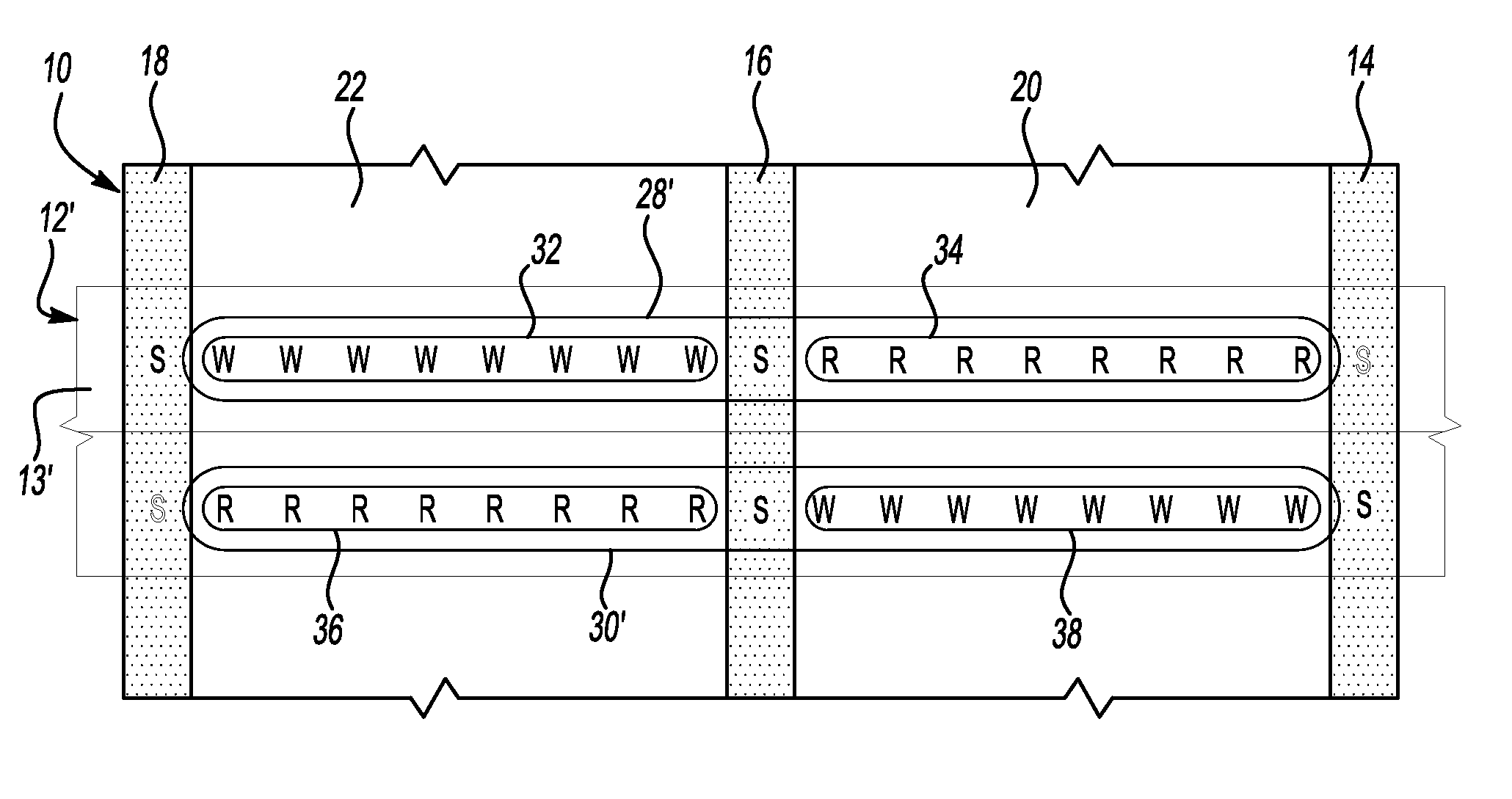
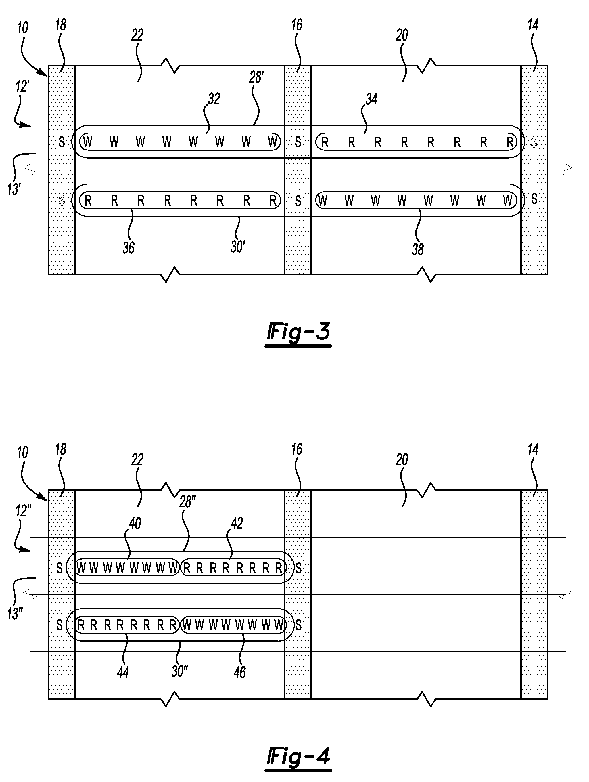
[0052]By separating the read elements from the write elements and by laterally aligning the read group and the write group of each array between two consecutive servo track sensors, the space between individual interactive elements is approximately half that between the individual interactive elements of either of the present invention or of the prior art tape head configuration. By reducing the space between the individual interactive elements of arrays 28″ and 30″, tape head 12″ is less susceptible to the dimensional changes of tape 10 caused by changes in temperature and atmospheric conditions. In this configuration, write group 40 would write data to only one-half of the space available in data zone 22. As configured in FIG. 4, the left half of data zone 22 would be written to by write group 40 as tape 10 moves in the reverse direction (towards the bottom of the page) while write group 46 would write data to the right half of the tape in data zone 22 as tape 10 moves in the forw...

second embodiment

[0053]The individual interactive elements of arrays 28″ and 30″ of tape head 12″ are disposed between 25 and 125 microns from one another. In other embodiments, the distance between the individual elements may be 80 microns. Additionally, while the second embodiment illustrated in FIG. 4 has cut the distance between individual interactive elements in half, the space between individual interactive elements may be reduced by any fractional amount and still achieve the benefits of the present invention. In such instances, additional arrays of interactive elements may be needed to cover the distance between lateral ends of a single data zone.

[0054]In the second embodiment illustrated in FIG. 4, not only does the depicted configuration address the concerns of the changing dimensions of tape 10, but this configuration also permits tape head 12″ to read data that was recorded using prior art tape heads. Alternate read elements from read group 42 and read group 44 are disposed in a lateral ...


PUM

PropertyMeasurementUnit
distanceaaaaaaaaaa
distanceaaaaaaaaaa
distanceaaaaaaaaaa

Abstract

A tape head assembly for writing data to and reading data from a tape includes a tape head member having an engagement surface that is configured to engage the tape as the tape moves past the tape head member. A plurality of arrays of interactive elements are supported on the engagement surface. Each array is longitudinally offset from each other array. Each individual array includes a read group having only read elements and a write group having only write elements. Each read group is laterally offset from each write group within each array.

Description

BACKGROUND OF THE INVENTION[0001]1. Field of the Invention[0002]The invention disclosed herein relates to the field of arranging interactive elements on a tape head configured to read electronic data stored on tape media.[0003]2. Background Art[0004]Tape heads that are configured to read electronic data stored on tape media, for example, magnetic tapes, are known. Magnetic tape conventionally include a plurality of servo tracks and a plurality of data zones. The data zones are arranged longitudinally along the magnetic tape. The servo tracks are also arranged longitudinally on the magnetic tape and bound the data zones. For example, a conventional tape may include two data zones and three servo tracks, a first and a third servo track being laterally spaced apart along the magnetic tape with the two data zones disposed between the first and third servo tracks. The second servo track is disposed along the center of the magnetic tape separating the two data zones.[0005]A conventional t...

Claims


Application Information

Patent Timeline
Patent Type & Authority Patents(United States)
IPC IPC(8): G11B5/48
CPCG11B5/4893G11B5/4976
Inventor MCKINSTRY, KEVIN D.CAMPOS, FRANCIS
Owner ORACLE INT CORP
Why Eureka
Try Eureka