Silicon microphone with enhanced impact proof structure using bonding wires

a technology of impact-proof structure and silicon condenser, which is applied in the direction of electrical transducers, piezoelectric/electrostrictive transducers, transducer types, etc., can solve the problems of stopper components complicating the fabrication process, and compatibility issues between stoppers

Active Publication Date: 2011-10-25
SHANDONG GETTOP ACOUSTIC
View PDF11 Cites 23 Cited by
  • Summary
  • Abstract
  • Description
  • Claims
  • Application Information

AI Technical Summary

Benefits of technology

[0005]One objective of the present invention is to provide a silicon microphone without a dedicated backplate component that has a design feature which prevents a large movement in the suspended diaphragm from breaking the device.
[0006]A further objective of the present invention is to provide a silicon microphone design according to the first objective that does not add complexity to the fabrication process.
[0008]In a first embodiment, the spring and diaphragm are essentially circular in shape, and the spring comprises a circular ring and a plurality of inner beams which is attached to the circular outer edge of the diaphragm. The spring is also comprised of a plurality of outer beams attached to the plurality of rigid pads of the anchors wherein one outer beam is connected to one rigid pad. Such a spring is formed to release in-plane stress and allow more out-plane flexibility. The diaphragm has a diameter slightly larger than the diameter of the underlying backside hole to avoid direct acoustic leakage.
[0009]The outer beams of the spring connect to a plurality of anchors which hold the diaphragm, spring, and perforated plates in place but allow movement of the diaphragm, perforated plates, and circular spring in a direction perpendicular to the substrate. Each rigid pad is disposed on a dielectric layer which acts as a spacer to define an air gap between the diaphragm and the substrate. One or more of the rigid pads have an overlying first electrode which is an island of a conductive metal that is connected by wiring to external circuitry. A second electrode of the same material composition is formed on the conductive substrate and is connected to a first electrode to complete a variable capacitor with one pole on the perforated plates and spring, and another pole on the substrate. Preferably, the diaphragm, perforated plates, spring, and rigid pads are coplanar and are made from the same polysilicon membrane layer and the dielectric spacer is a silicon oxide layer. Perforations formed in the perforated plates and in the spring are holes that may be arranged in various designs to allow removal of an underlying dielectric layer during the fabrication process. The holes also allow air ventilation and thus reduce the air damping in the narrow air gap below the diaphragm, spring, and perforated plates during vibrations.
[0012]Another important feature is the formation of a plurality of bonding pads outside the outer edge of the spring that enable bonding wires to cross over the diaphragm from a first bond site to a second bond site in a variety of patterns. Thus, if there are “n” bonding pads arrayed on the membrane layer along the outer edge of the spring, the number of bonding wires crossing the diaphragm is “n / 2” and these wires are used advantageously to prevent vibrations in the diaphragm and spring from becoming too large and causing device breakage.
[0013]In a second embodiment, the perforated spring has three types of slots that may be referred to as inner slots, middle slots, and an outer continuous slot, and the perforated plates are omitted. Although the diaphragm and spring may have a rectangular, square, or other polygonal shapes, the exemplary embodiment shows a circular diaphragm surrounded by a circular spring. The diaphragm may have ribs radiating from a center point to the outer edge in order to strengthen the diaphragm. The circular spring is essentially comprised of two interconnected ring springs and a plurality of perforated beams connecting the outer edge of the outer ring spring to a plurality of anchors. The inner ring spring is attached to certain portions of the edge of the diaphragm. The outer ring spring is attached via perforated beams to a plurality of rigid pads which are anchored to the conductive substrate through a dielectric layer. Inner and outer ring springs are perforated with holes. Furthermore, there is a plurality of “n” bonding pads outside the outer edge of the perforated spring to allow a plurality of “n / 2” bonding wires to cross over the diaphragm or circular spring and thereby restrict the motion of the diaphragm and perforated circular spring in a direction perpendicular to the backside hole.

Problems solved by technology

However, the stopper components complicate the fabrication process and there may be a compatibility issue between the stopper and the silicon membrane to which it is attached.

Method used


Image

  • Silicon microphone with enhanced impact proof structure using bonding wires
  • Silicon microphone with enhanced impact proof structure using bonding wires
  • Silicon microphone with enhanced impact proof structure using bonding wires

Examples


first embodiment

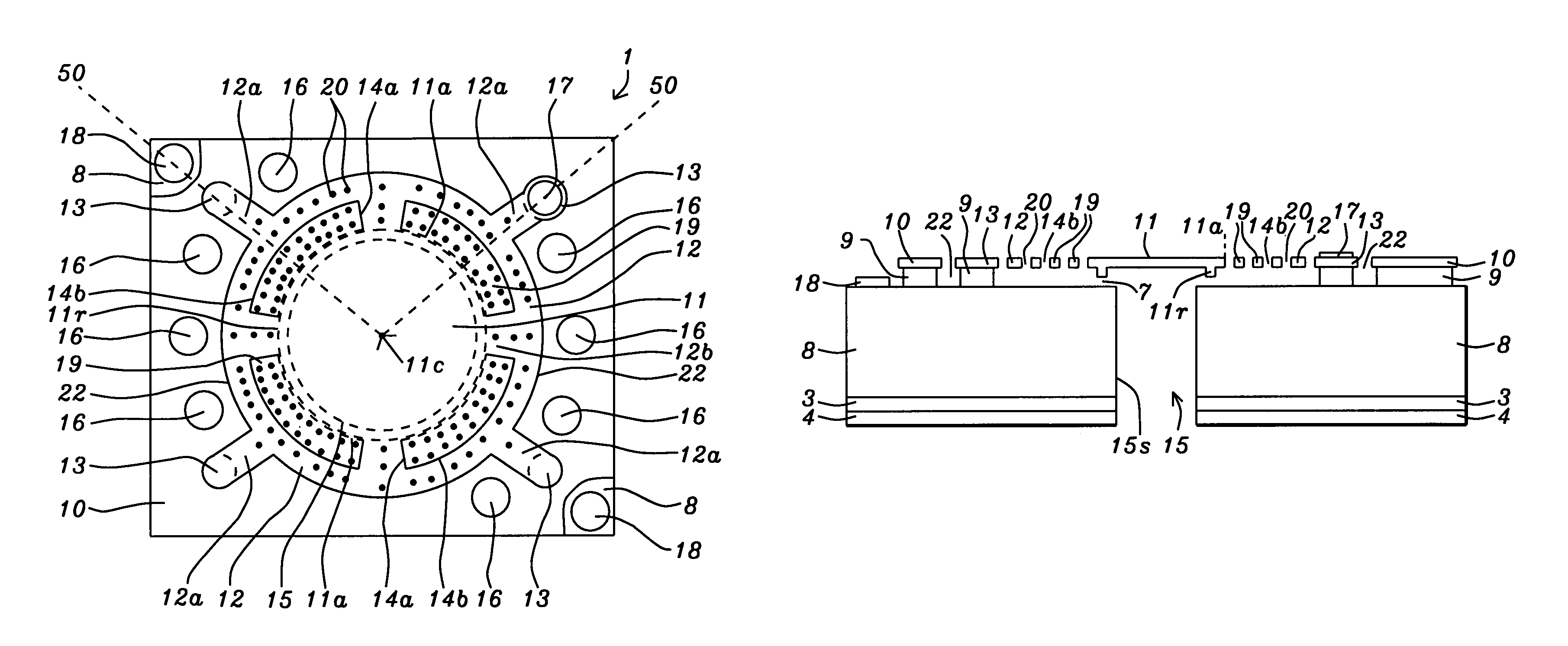
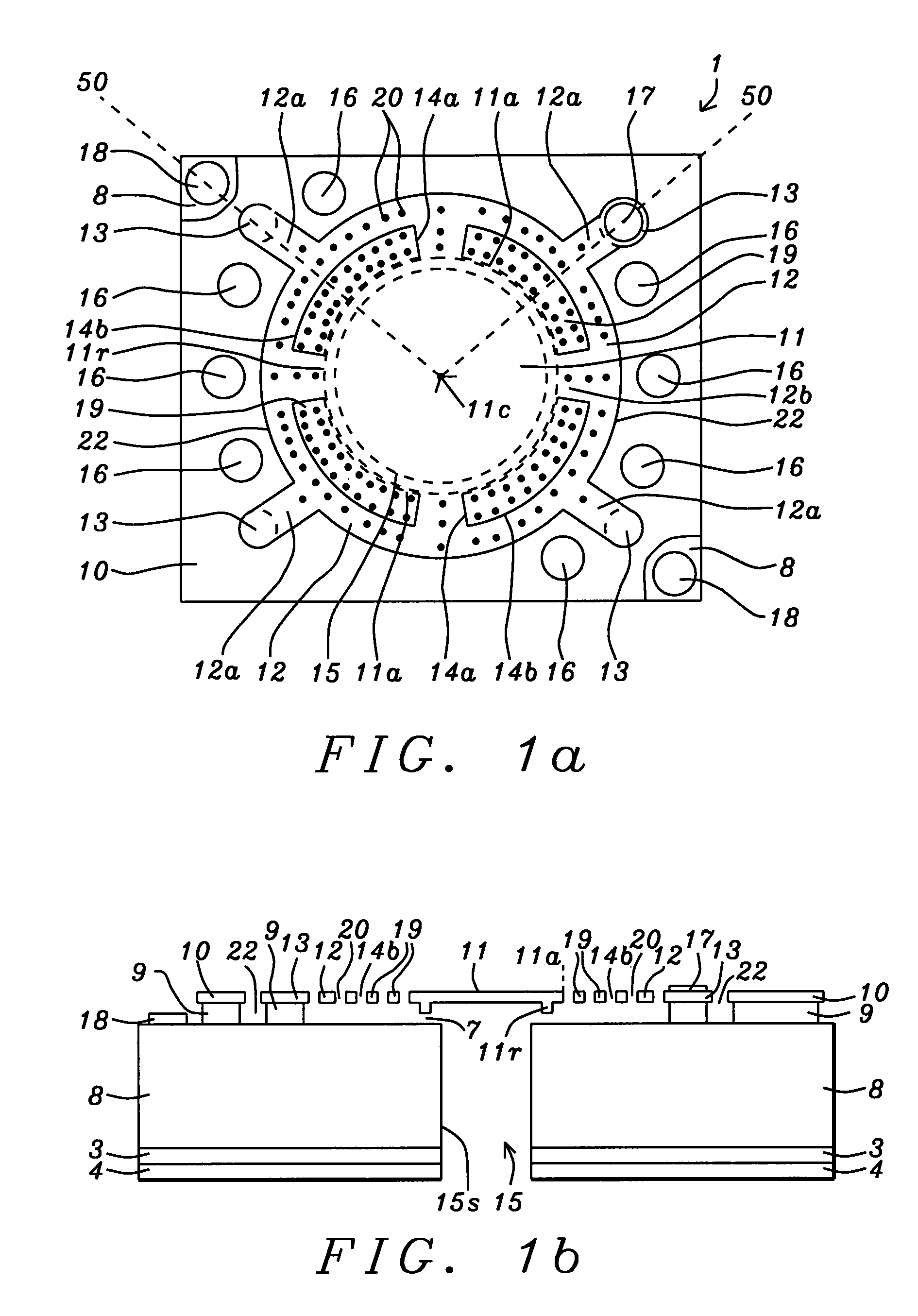
[0034]Referring to FIG. 1a, a backplateless silicon microphone 1 having improved impact resistance is depicted from a top view. The silicon microphone 1 is fabricated from a membrane layer 10 on a substrate 8 such as silicon which preferably has low resistivity. Optionally, the substrate 8 may be glass with a conductive layer formed thereon. The silicon microphone 1 is based on a membrane layer 10 that is fabricated into a diaphragm which is suspended over an air gap and surrounded by a plurality of perforated plates 19 and a spring 12. The spring 12 is held to the substrate by a plurality of anchors 13. Each of the perforated plates 19 has four sides wherein one side is attached to the outer edge 11a of the diaphragm and the other three sides are formed by slots 14a, 14b. In the exemplary embodiment, the diaphragm 11 is essentially planar and has a circular shape with an outer edge 11a that extends beyond the underlying backside hole 15. In addition, the spring 12 has a circular sh...

second embodiment

[0056]Referring to FIG. 7a, a topview is illustrated of a second embodiment for a silicon microphone 60 of the present invention. In the exemplary embodiment, a circular diaphragm 31 having an outer edge 31a is surrounded by a spring 33 that is essentially circular except for a plurality of beams 33a that protrude outward from circular spring 33. However, the present invention also encompasses an embodiment wherein the shape of the diaphragm 31 and surrounding spring 33 are polygonal. The diaphragm 31 and spring 33 are coplanar and the outer edge 31a extends beyond the circular perimeter 35 of an underlying backside hole. The diaphragm31 may be comprised of doped silicon, doped polysilicon, Au, Ni, Cu, or other semiconductor materials or metals and is supported along its outer edge 31a by attachment to the inner edge of the circular spring 33 that is comprised of the same material and has the same thickness as the diaphragm 31. The plurality of “m” beams 33a serve as connections to ...

third embodiment

[0071]The spring 33 in the third embodiment is considered to have a double folded spring configuration wherein an inner folded spring portion is formed between the inner slots 34b and the middle slots 34a and an outer folded spring portion is formed between the middle slots and the outer slot 34c.

[0072]Other aspects of the second embodiment are carried forth in the third embodiment such as a plurality of “n” bonding pads 36 formed outside the outer slot 34c on membrane layer 30 and preferably between adjacent pads 32. There is a first electrode 37 formed on one or more pads 32 and one or more second electrodes 38 formed on substrate 28. From a top view, the sides (outer edges) of the diaphragm 31 and sealing ribs 31r are a greater distance (x, y direction) from the diaphragm center 31c than the backside hole 35 which may have a square shape. The third embodiment also encompasses a bonding wire protection scheme in which “n / 2” bonding wires (not shown) are used to connect the “n” bo...


PUM


Abstract

A backplateless silicon microphone and a wire protection method for improved impact resistance are disclosed. A circular diaphragm is surrounded by a circular spring having a plurality of slots and perforations to facilitate air damping reduction, release of in-plane stress, and improve out-plane flexibility. Anchored at a substrate, the circular spring holds the silicon microphone suspended over a backside hole in the substrate but allows the diaphragm to vibrate perpendicular to the substrate. A microphone variable capacitor is formed between the perforated spring and substrate. Slot size is minimized to prevent particles from entering an underlying air gap. A plurality of “n” bonding pads near the outer edge of the circular spring are connected by “n / 2” bonding wires that serve as a stopper to restrict an upward motion of the diaphragm. The bonding wires may cross each other to enable lower loop height for more effective resistance to impact.

Description

RELATED PATENT APPLICATION[0001]This application is related to the following: Ser. No. 11 / 500,114, filing date Aug. 7, 2006; assigned to a common assignee and herein incorporated by reference in its entirety.FIELD OF THE INVENTION[0002]The invention relates to a sensing element of a silicon condenser microphone and a method for making the same, and in particular, to a silicon microphone structure without a dedicated backplate that employs crossed wire bonding above a diaphragm element to prevent breakage from large diaphragm movements.BACKGROUND OF THE INVENTION[0003]In the fast growing consumer electronic product market, there is increasing competition not only in product functionality but also in product reliability performance. For hand held electronic gadgets, the impact proof requirement is becoming more and more stringent. It is not unusual now to require a hand held device like a mobile phone to survive the impact from a 5000 gram weight and / or a free drop from a height of 1....

Claims


Application Information

Patent Timeline
Patent Type & Authority Patents(United States)
IPC IPC(8): H04R25/00H04R19/00H01L21/00
CPCH04R19/04
Inventor ZHE, WANGCHOONG, CHONG SER
Owner SHANDONG GETTOP ACOUSTIC
Why Eureka
Try Eureka