
Computer virtualization apparatus and program and method therefor

a computer and virtualization technology, applied in the field of tlb virtualization technique, can solve the problems of affecting the performance of the computer, so as to achieve the effect of not deteriorating performan

Inactive Publication Date: 2011-10-25
HITACHI LTD
View PDF1 Cites 4 Cited by
  • Summary
  • Abstract
  • Description
  • Claims
  • Application Information

AI Technical Summary

Benefits of technology

[0021]The present invention has been devised in view of the problems and it is an object of the present invention to provide a computer virtualization apparatus that can eliminate, under a restriction that performance is not deteriorated, the limitation on the number of computers that can simultaneously operate.

Problems solved by technology

Therefore, the OS does not perform unintended conversion.
This method is excellent in that, when a guest OS is switched, it is unnecessary to execute processing for clearing a TLB entry, which takes a long processing time.
However, the number of bits for identifying virtual computers and the number of bits for identifying memory spaces are limited.
In other words, the number of virtual computers that can simultaneously operate on a computer and the number of memory spaces are limited.
In particular, in a method of virtualizing plural computers and aggregating the virtualized computers in one computer, there is a significant problem in that the number of computers that can simultaneously operate is limited.

Method used


Image

  • Computer virtualization apparatus and program and method therefor
  • Computer virtualization apparatus and program and method therefor
  • Computer virtualization apparatus and program and method therefor

Examples


second embodiment

[0101]In the first embodiment, an entry once registered in the guest RID-physical RID mapping table 137 is not deleted unless the entry is selected as a deletion object RID in step 803 shown in FIG. 8.

[0102]In the guest OSs 111, in general, one or more memory spaces are exclusively allocated to one process. In other words, the memory spaces and guest RIDs allocated to the memory spaces are discarded when the process is finished.

[0103]Until the guest OSs allocate the discarded guest RIDs to memory spaces allocated to another process again, entries of the guest RIDS are not used. When the process is finished, the entries of the guest RIDs associated with the finished process may be deleted from the guest RID-physical RID mapping table 137.

[0104]The hypervisor 13 can detect that a guest uses a new RID with setting of a value in an RR as an opportunity. However, there is no method of detecting the finish of the process. Therefore, the hypervisor 13 cannot delete the entries at timing of...

third embodiment

[0119]Depending on the architecture of the CPU, there is an operation for deleting all entries of a TLB. In the configuration including the shadow TLB, when the operation for deleting all entries is emulated, all shadow TLB entries have to be deleted in the operation. This processing takes time.

[0120]In a third embodiment of the present invention, in order to the increase speed of emulation for deleting all TLB entries, the configuration and the processing procedure in the second embodiment are further expanded.

[0121]In the third embodiment, at a point of deletion of all TLB entries, all entries in the guest RID-physical RID mapping table 137 for a relevant guest ID are invalidated and another physical RID is allocated to a virtual RID set in a physical RR at present. According to this procedure, a physical RID included in an invalidated entry is not set in a physical RR and an entry of a shadow TLB including the physical RR is not referred to from the physical CPU 12. In other word...


PUM


Abstract

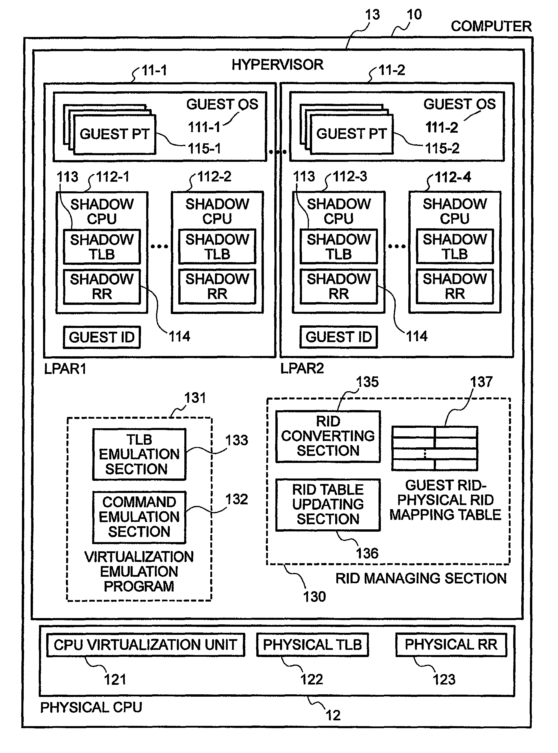
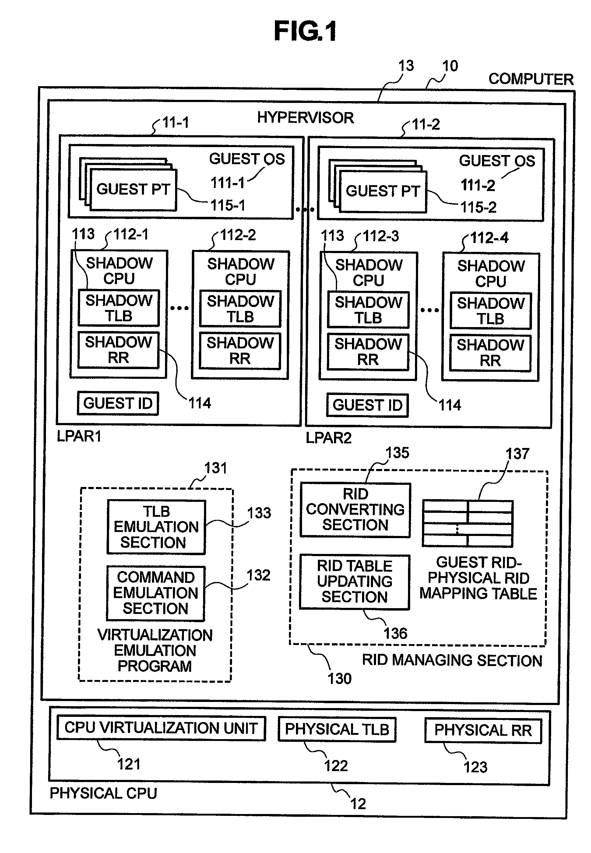
A hypervisor prepares a guest region identifier (RID)-physical region identifier (RID) mapping table for dynamically registering and managing items and performs RID conversion using the guest RID-physical RID mapping table. When the mapping table is used, since it is unnecessary to provide a specific information area representing logical partitions (LPARs) corresponding to respective guests in an RID to be converted, there is no limitation concerning the number of LPARs and a problem in operation can be eliminated.

Description

CLAIM OF PRIORITY[0001]The present application claims priority from Japanese application serial no. JP2007-330374, filed on Dec. 21, 2007, the content of which is hereby incorporated by reference into this application.BACKGROUND OF THE INVENTION[0002]1. Field of the Invention[0003]The present invention relates to a TLB virtualization technique in a computer virtualization technique.[0004]2. Description of the Related Art[0005]In recent years, a computer virtualization technique for causing plural virtual computers to simultaneously operate on a computer based on the architecture of a personal computer (hereinafter referred to as PC) has been attracting attention. Advantages such as a reduction in the number of actually operating computers and facilitation of operation and configuration changes through encapsulation of hardware are spreading in the market.[0006]Many techniques concerning virtualization of computers such as main frames have been developed so far. However, in order to ...

Claims


Application Information

Patent Timeline
Patent Type & Authority Patents(United States)
IPC IPC(8): G06F12/00
CPCG06F12/1036G06F9/45558G06F2009/45583G06F2212/152
Inventor TAKASHIGE, SOUICHISEKIGUCHI, TOMOKIHASEGAWA, TOMOHIDE
Owner HITACHI LTD
Learn More