Head gimbal assembly using near-field light and information recording and reproducing apparatus including the same
a near-field light and assembly technology, applied in the direction of head support, record information storage, instruments, etc., can solve the problems of insufficient light supply, inability to collect enough energy to a microscopic region comparable to 1-bit data, and inability to record information in recording media, etc., to achieve stable levitation, stable performance, and enhance the quality
- Summary
- Abstract
- Description
- Claims
- Application Information
AI Technical Summary
Benefits of technology
Problems solved by technology
Method used
Image
Examples
first embodiment
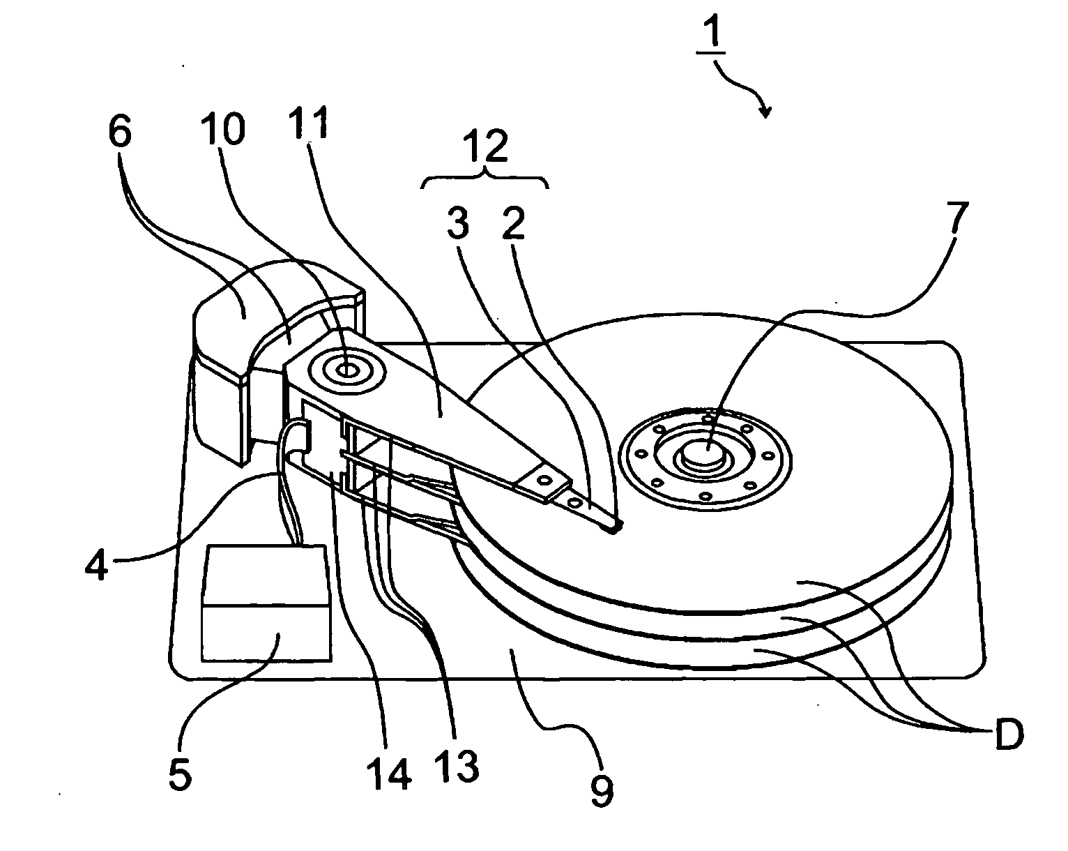
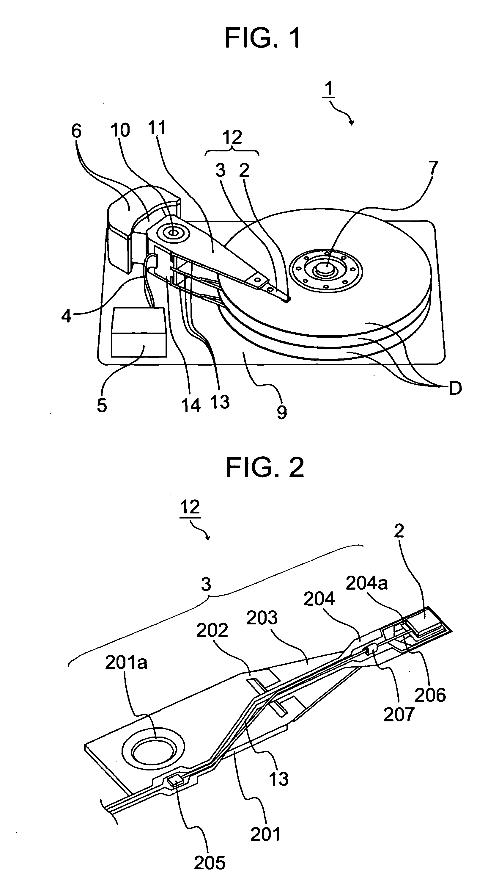
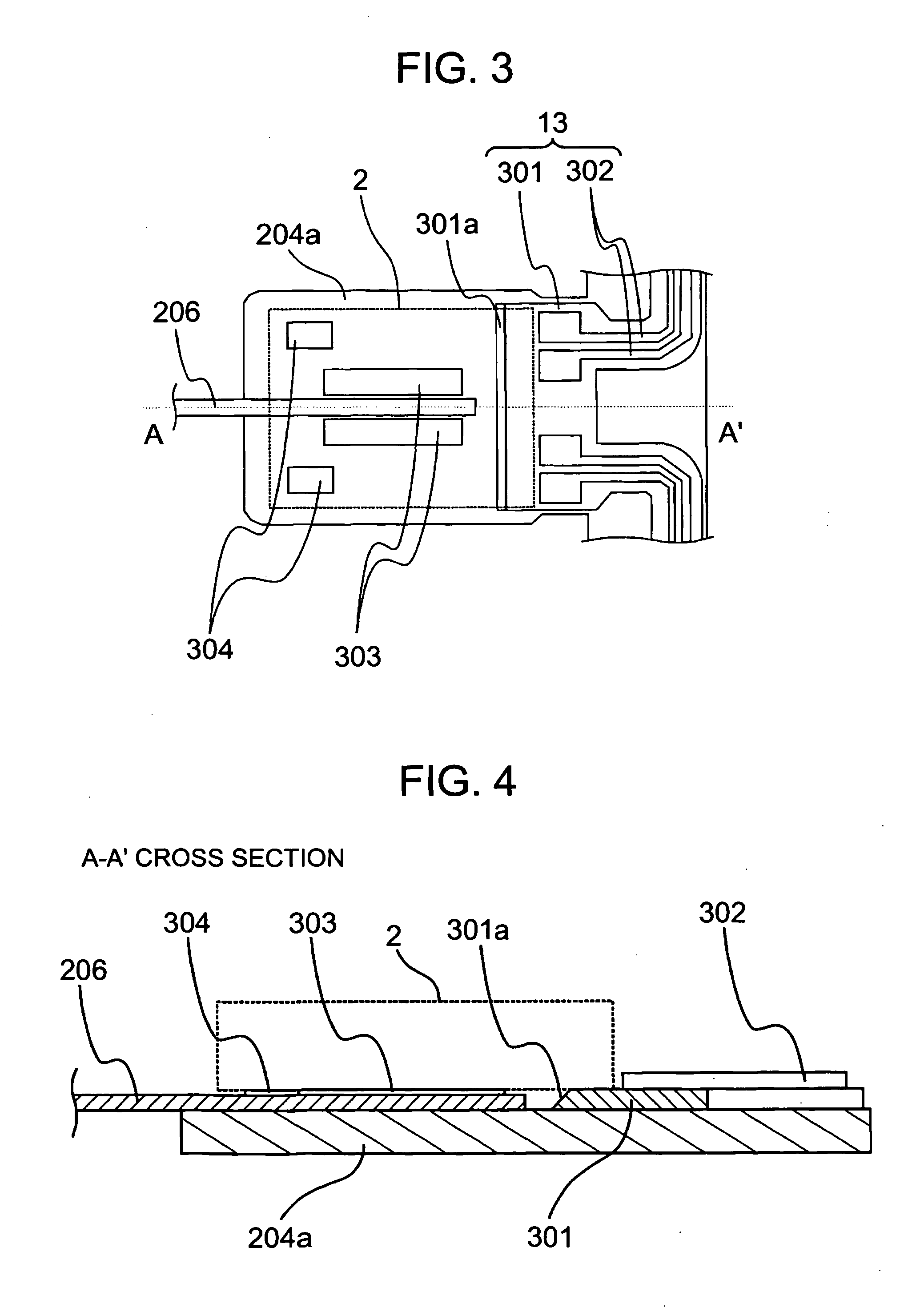
[0067]Hereinafter, a first embodiment of the invention will be descried with reference to FIG. 1 through FIG. 4. FIG. 1 is a view showing the configuration of an information recording and reproducing apparatus 1 of this embodiment. The information recording and reproducing apparatus 1 of this embodiment is an apparatus that writes information into a recording medium D having a magnetic recording layer by a thermal-assist magnetic recording method.
[0068]As is shown in FIG. 1, in the information recording and reproducing apparatus 1 of this embodiment, a slider 2 is fixed to a suspension 3 and the suspension 3 is fixed to a carriage 11. The slider 2 and the suspension 3 are together called a head gimbal assembly 12. Disc-shaped recording media D are rotated in a predetermined direction by a spindle motor 7. The carriage 11 is rotatable about a pivot 10. The carriage 11 is rotated by actuators 6 controlled by a control signal from a control portion 5. The carriage 11 is capable of loca...
second embodiment
[0078]Hereinafter, a second embodiment of the invention will be described with reference to FIG. 5. Like components are labeled with like reference numerals with respect to the first embodiment above and a detailed description is omitted herein.
[0079]This embodiment is different from the first embodiment above in that the end face of the flexible substrate 301 is notched in a rectangular shape in a portion opposing the optical fiber 206 and a mirror surface 501 is provided to one surface opposing the optical fiber 206 among the side surfaces of this notch. As in the first embodiment above, the mirror surface 501 is an inclined plane inclined by 45 degrees with respect to the longitudinal direction of the optical fiber 206 and coated with metal.
[0080]Owing to this configuration, it becomes possible to introduce light to where it is the closest possible proximity to the flow-out end of the slider 2 while ensuring the size of a region of the flexible substrate 301 on which the slider 2...
third embodiment
[0081]Hereinafter, a third embodiment of the invention will be described with reference to FIG. 6. Like components are labeled with like reference numerals with respect to the first embodiment above and a detailed description is omitted herein. This embodiment is different from the first embodiment above in that of the end faces of each fiber guide 601, one end face opposing the mirror surface 301a is formed as an inclined plane 602.
[0082]Owing to this configuration, a dicing blade with an edge having a V-shaped cross section or a trapezoidal cross section can be used when forming the inclined plane from which the mirror surface 301a is obtained. The structure can be therefore processed readily at a low cost. Further, because a distance between the fiber guides 601 and the mirror surface 301a can be shortened, the optical fiber 206 can be fixed up to the vicinity of the mirror surface 301a with the fiber guides 601. Hence, the optical axis of light exiting from the optical fiber 206...
PUM
 Abstract
Description
Claims
Application Information
 - R&D
- Intellectual Property
- Life Sciences
- Materials
- Tech Scout
- Unparalleled Data Quality
- Higher Quality Content
- 60% Fewer Hallucinations
Browse by: Latest US Patents, China's latest patents, Technical Efficacy Thesaurus, Application Domain, Technology Topic, Popular Technical Reports.
© 2025 PatSnap. All rights reserved.Legal|Privacy policy|Modern Slavery Act Transparency Statement|Sitemap|About US| Contact US: help@patsnap.com


