Liquid container

a liquid container and liquid technology, applied in printing and other directions, can solve the problems of large deflection range, increased shock absorption material thickness, and pinched between them, and achieve the effect of high reliability and cost increas

Active Publication Date: 2011-11-01
CANON KK
View PDF23 Cites 27 Cited by
  • Summary
  • Abstract
  • Description
  • Claims
  • Application Information

AI Technical Summary

Benefits of technology

This invention provides a highly reliable liquid container which, when it is strongly impacted, can prevent a possible damage to a flexible film that forms a liquid accommodation chamber, without causing a reduction in a liquid accommodation efficiency or a significant cost increase.
With this invention, when the liquid container is strongly impacted, a shock absorbing member absorbs the impact of the plate member by using a recessed inner space in a cover member, so that a flexible film can be protected against being damaged without reducing a liquid accommodation efficiency. Further, with use as a shock absorbing member of a shock absorbing sheet that can easily be laid at a desired position and flexibly conform to the shape of a recessed portion, the manufacturing cost of the liquid container can be minimized.
When the flexible film that forms a liquid accommodation chamber is formed into a convex shape, portions of the plate member facing the thin parts of the film may be provided with a notch to prevent a possible damage of the flexible film more effectively.

Problems solved by technology

This strong collision may result in the film 102 interposed between the plate member 105 and the cover member 106 being pinched between them and damaged.
In these measures, however, since an impact is absorbed by the shock absorbing material being deflected, to absorb a high energy produced by the impact of the falling ink tank requires increasing the thickness of the shock absorbing material to set the deflection range large.
But setting the thickness of the shock absorbing material large limits a range in which the plate member is allowed to move, reducing the ink accommodation space, which in turn is likely to reduce the amount of ink that can be filled into the accommodation space.
Another problem is that the shock absorbing material that is thin and still able to absorb shocks is limited to special materials such as silicone gel-like materials.
Generally, a material with such a high energy absorbing capability is very expensive and may lead to a substantial increase in cost of the ink tank.
Further, since the increased ink tank capacity results in an increase in its weight and therefore an impact at time of fall, which in turn increases a possibility of the film damage.
However, this approach, although it can make the easily damaged film portions thick, increases the thickness of other portions more than necessary and therefore a film rigidity.
As a result, the film behavior is not smooth as the ink in the ink tank is consumed.
This in turn raises possibilities of the negative pressure in the ink accommodation space abruptly changing and of the ink in the accommodation space failing to be consumed completely.
Simply rounding the corner portions of the plate member, however, cannot deal with the characteristic thickness distribution of the convex film formed by a concave forming die, as described later.
It is also necessary to reduce the size of the plate member, giving rise to a possibility of the ink accommodation efficiency reducing significantly.

Method used


Image

  • Liquid container
  • Liquid container
  • Liquid container

Examples


first embodiment

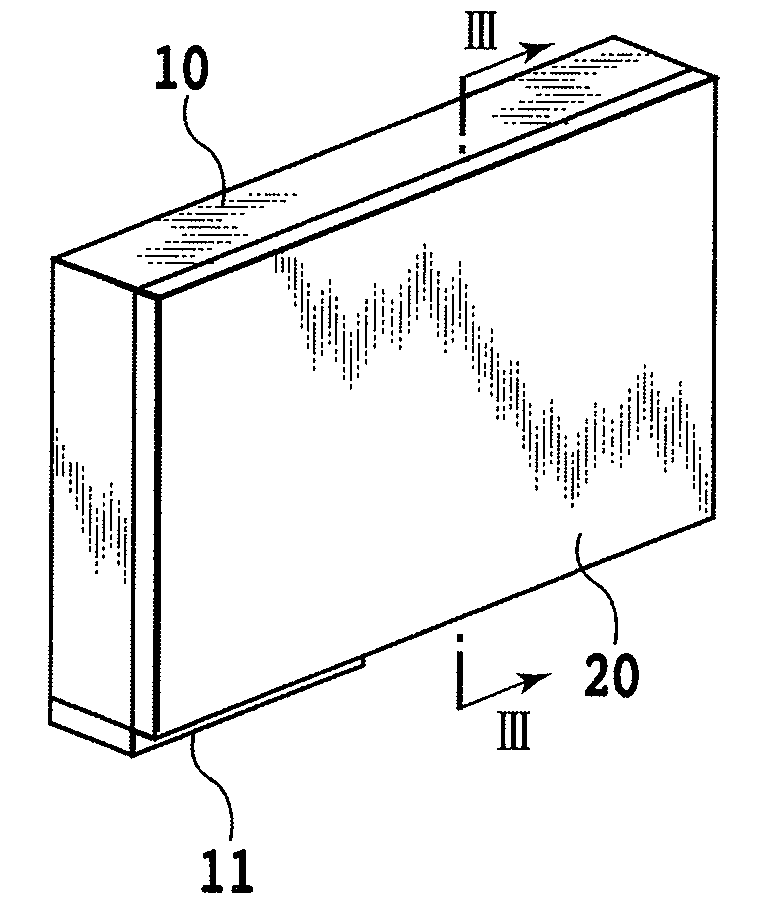
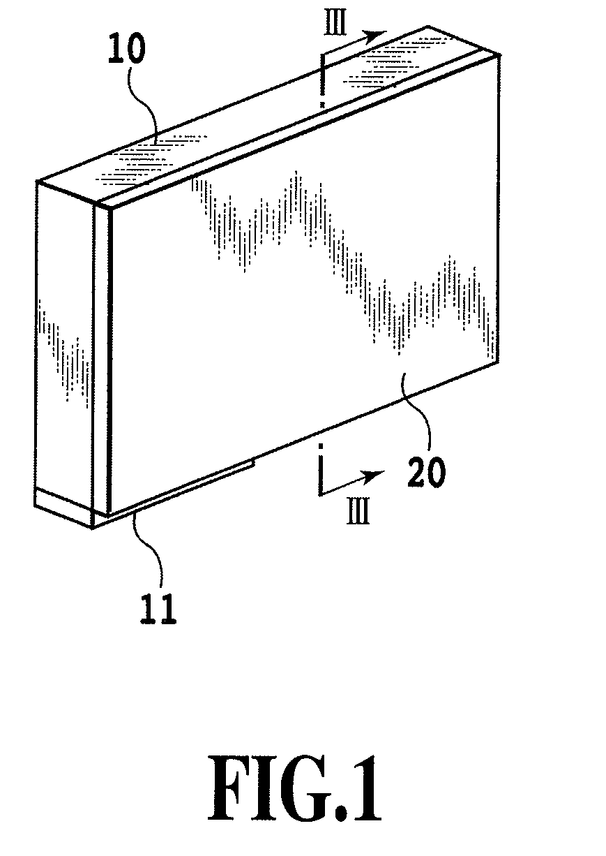
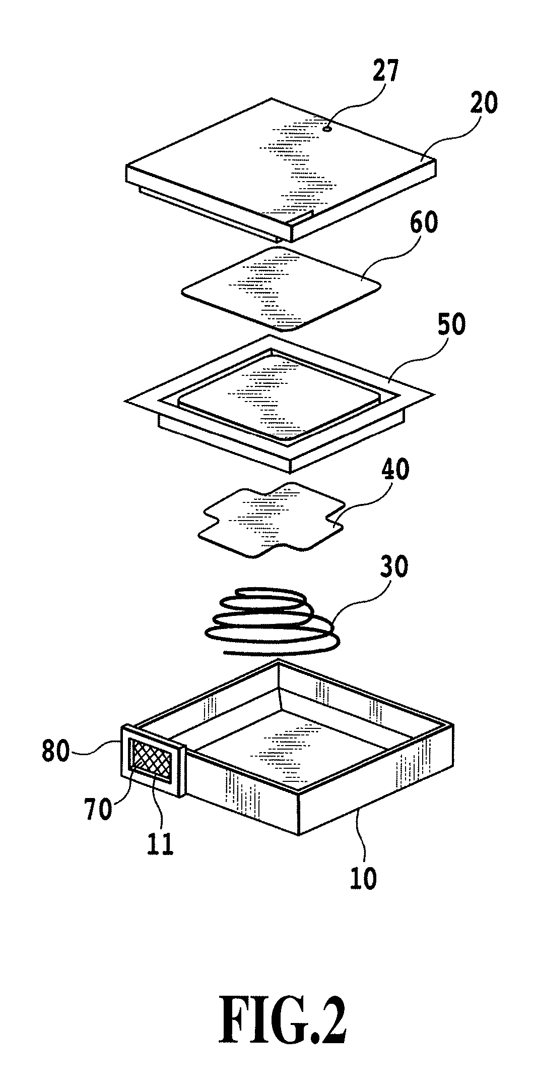
FIG. 1 to FIG. 11 are drawings to explain the first embodiment of this invention. FIG. 1 is an outline perspective view of an ink tank in the first embodiment, and FIG. 2 is an exploded perspective view of the ink tank.

The ink tank of this embodiment, as shown in an outline perspective view of FIG. 1, comprises a case 10 and a cover member 20. An ink accommodation space is formed in the ink tank as a liquid accommodation space (liquid accommodation chamber), as described later. At its bottom the case 10 has an ink supply port 11 from which to supply ink from an ink accommodation space to a print head not shown.

As shown in FIG. 2, the ink tank has the case 10, a spring member 30, a plate member 40, a flexible film 50, a shock absorbing sheet 60, the cover member 20, a meniscus forming member 70 and a holding plate 80. The case 10 may, for example, be formed of a resin material such as polypropylene. Held at its circumferential part by the holding plate 80, the meniscus forming member...

second embodiment

Next, the construction of an ink tank according to a second embodiment of this invention will be explained by referring to FIG. 12. FIG. 12 is a front view of a cover member 20 and a shock absorbing sheet 60, combined together to form shock absorbing portions 90.

The ink tank of this embodiment is so constructed as to be able to prevent damages to the film 50 if the ink tank falls with its flat outer surface landing on the ground. That is, the ink tank can prevent damages to the film 50 even if the film 50 has low stiffness and is liable to damage and if not only the corner portions 41A but also the edge portions 42A of the plate member 40 strike the inner surface 22 of the cover member 20.

The recessed portions 23 of the cover member 20 in this embodiment are wider than those of the first embodiment. That is, the size of the recessed portions 23 is so set that, if the plate member 40 moves in an allowable range inside the rib 21, the recessed portions 23 always oppose the corner port...

third embodiment

Next, the construction of an ink tank according to a third embodiment of this invention will be explained by referring to FIG. 14A, FIG. 14B, FIG. 15 and FIG. 24A-24C. FIG. 14A is a front view showing a recessed portion 23 of the cover member 20 and a shock absorbing sheet 60, combined together to form a shock absorbing portion 90. FIG. 14B is a cross-sectional view taken along the line XIVB-XIVB of FIG. 14A. FIG. 15 is a cross-sectional view of the ink tank of this embodiment taken along the line III-III of FIG. 1. FIG. 24A is a perspective view of the cover member of FIG. 14A. FIG. 24B is an enlarged view of a portion XXIVB of FIG. 24A. FIG. 24C is a cross-sectional view taken along the line XXIVC-XXIVC of FIG. 24A.

As described above, when the ink tank falls and hits the ground, the plate member 40 moves in the gravity direction and at the same time tilts to move its impacting side toward the cover member 20. At this time, the plate member 40 may first hit the rib 21 of the cover ...


PUM


Abstract

This invention provides a highly reliable liquid container without degrading a liquid accommodation efficiency or increasing a substantial cost. When the liquid container is impacted, the liquid container can protect against damage the flexible film that forms the liquid accommodation chamber. The recessed portion is provided on the inner surface of the cover member facing the plate material. Provided at the opening of the recessed portion is the shock absorbing sheet that elastically deforms into the recessed portion when the plate member is impacted.

Description

BACKGROUND OF THE INVENTION1. Field of the InventionThe present invention relates to a liquid container to accommodate a variety of kinds of liquids, such as printing inks and liquids specially designed to improve ink fixing performance. Such a liquid container may include an ink tank detachably mounted in an ink jet printing apparatus.2. Description of the Related ArtAn ink jet printing apparatus prints an image on a print medium by supplying ink from an ink tank to a print head and ejecting ink from the print head. A so-called serial type ink jet printing apparatus has a carriage mountable a print head and performs printing by ejecting ink onto a print medium from ejection nozzles of the print head mounted on the carriage as the carriage is moved relative to the print medium. A so-called full-line type ink jet printing apparatus uses a print head having ejection nozzles arrayed over a range matching a width of a print medium. The full-line type performs printing by ejecting ink fr...

Claims


Application Information

Patent Timeline
Patent Type & Authority Patents(United States)
IPC IPC(8): B41J2/175
CPCB41J2/17513B41J2/17553B41J2/17556B41J2002/17516
Inventor NANJO, TATSUOKOTAKI, YASUOOHASHI, TETSUYAKUBO, KOICHI
Owner CANON KK
Why Eureka
Try Eureka