Liquid dispensing brush assembly for a floor scrubber

a floor scrubber and liquid dispensing technology, applied in the direction of brushes, burners, artistic surface treatment, etc., can solve the problems of wasting energy, time, and possibly even distressing the floor itsel

Inactive Publication Date: 2011-11-01
JORDAN POWER & EQUIP
View PDF3 Cites 9 Cited by
  • Summary
  • Abstract
  • Description
  • Claims
  • Application Information

AI Technical Summary

Benefits of technology

[0007]The device of the present invention comprises a floor scrubber that includes a housing having a plurality of brush assemblies mounted therein. Each brush assembly is connected to a liquid supply by a tube. A disperser is mounted on each brush assembly and cleaning liquid flows from the liquid supply onto the disperser. As the brush assembly is rotated, the disperser rotates in unison with the assembly and the cleaning liquid is dispersed onto the bristles and onto the floor surface to be cleaned. The disperser includes a plurality of fins that aid in propelling the cleaning fluid onto the bristles.

Problems solved by technology

Firstly, the operator may squirt the liquid from a container directly onto the floor.
Secondly, some scrubbing machines include a tube that terminates intermediate a plurality of scrubber heads.
This procedure requires extra cleaning passes of the scrubber on the flooring, which leads to wasted energy, time, and possibly even distress to the floor itself.

Method used


Image

  • Liquid dispensing brush assembly for a floor scrubber
  • Liquid dispensing brush assembly for a floor scrubber
  • Liquid dispensing brush assembly for a floor scrubber

Examples


Embodiment Construction

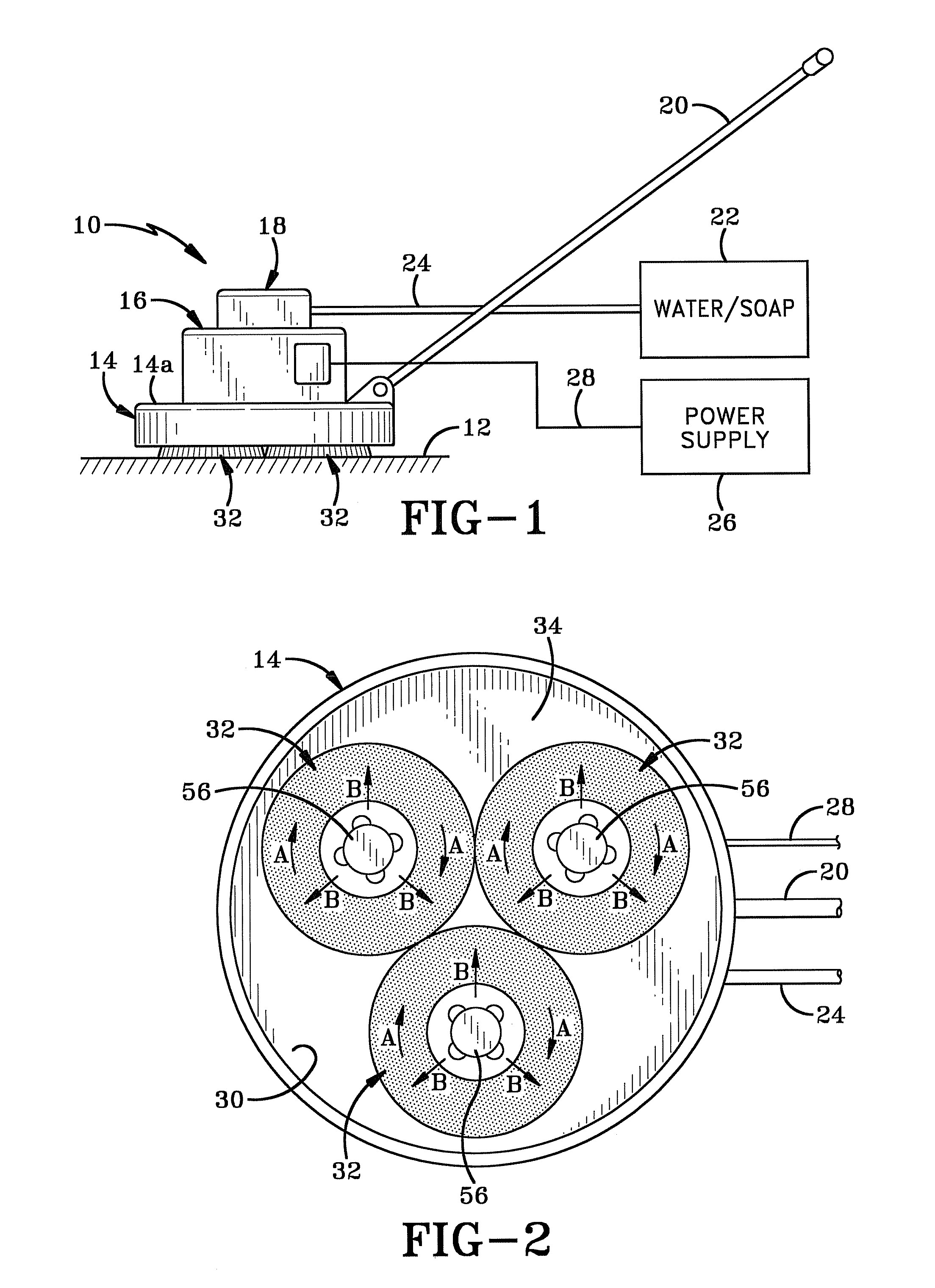
[0016]As shown in FIG. 1, a floor scrubber 10 rests on a floor surface 12. Floor scrubber 10 comprises a rotatable brush compartment 14, a motor compartment 16, and a liquid compartment 18. A handle 20 is pivotally mounted onto brush compartment 14 and is used to guide scrubber 10 over surface 12. A remote liquid supply 22 is operatively connected to liquid compartment 18 through a suitable means such as a hose 24. Soap may be added to the liquid supply 22 and introduced to liquid compartment 18 through hose 24. Alternatively, soap may be directly introduced into liquid compartment 18 and liquid supply 22 may provide water only. A remote power supply 26 is operationally connected via a cord 28 to motor compartment 16.

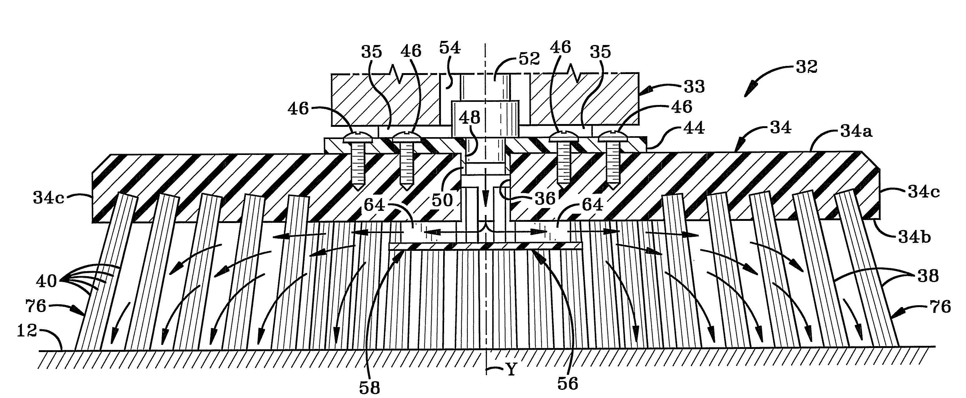
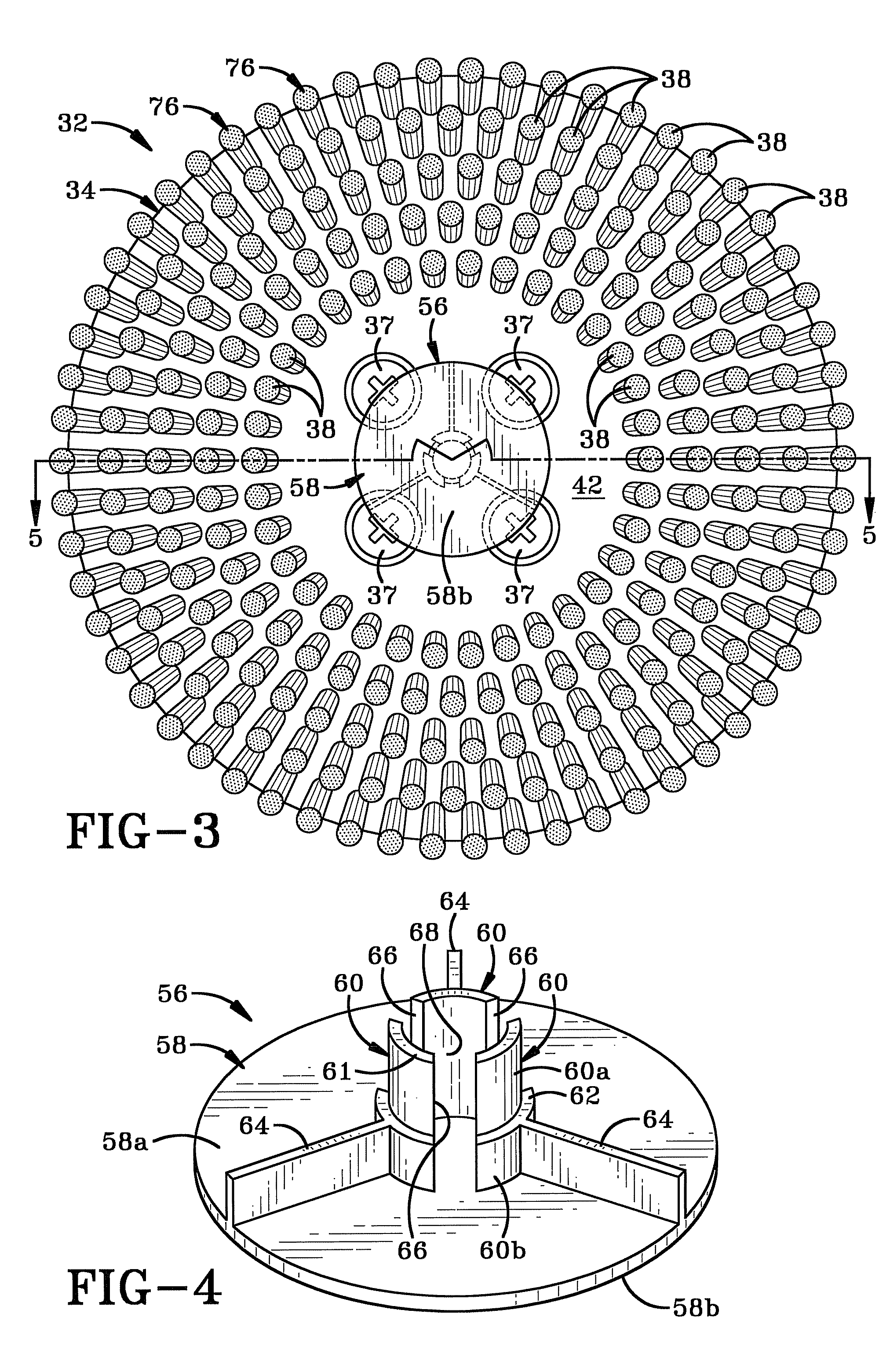
[0017]Referring to FIG. 2, brush compartment 14 is a housing that defines a downward facing cavity 30. Three substantially identical brush assemblies 32 are mounted within brush compartment 14. Brush assemblies 32 extend outwardly from under brush compartment 14 to enga...


PUM


Abstract

A floor scrubber that includes a housing having a plurality of brush assemblies mounted therein. Each brush assembly is connected to a liquid supply by a tube. A disperser is mounted on each brush assembly and cleaning liquid flows from the liquid supply onto the disperser. As the brush assembly is rotated, the disperser rotates in unison with the assembly and the cleaning liquid is dispersed onto the bristles and onto the floor surface to be cleaned. The disperser includes a plurality of fins that aid in propelling the cleaning fluid onto the bristles.

Description

BACKGROUND OF THE INVENTION[0001]1. Technical Field[0002]The invention relates to machinery for scrubbing floors. More particularly, the invention relates to a brush assembly. Specifically, the invention relates to dispenser disk mounted on a brush assembly and which delivers cleaning liquid through a tube and onto fins that cause the liquid to be centrifugally dispersed upon rotation of the brush assembly.[0003]2. Background Information[0004]Household flooring can experience a range of soiling, from ground-in dirt to pet stains. Over the years, floor cleaning has evolved from scrubbing on one's hands and knees with a rag and soap, to machines specifically designed for this purpose.[0005]Floor scrubbing machines can have many different configurations, but in general all include brush assemblies that incorporate scrubbing bristles, and a powered motor for driving the rotation of the brush assembly. Cleaning liquids are applied to the floor prior to rotation of the brush assembly in o...

Claims


Application Information

Patent Timeline
Patent Type & Authority Patents(United States)
IPC IPC(8): A46B11/04A47L11/00B05B3/10B05B1/26
CPCA46B13/008A46B13/04A47L11/283A47L11/4038A47L11/4088
Inventor JORDAN, TODD A.
Owner JORDAN POWER & EQUIP
Why Eureka
Try Eureka