Pulsed-neutron formation density

a technology of pulsed neutron and formation density, which is applied in the field of pulsed neutron density logging tools, can solve the problem that the bulk density measurement made with a pulsed neutron logging tool may not match the actual bulk density

Inactive Publication Date: 2011-11-01
HALLIBURTON ENERGY SERVICES INC
View PDF25 Cites 13 Cited by
  • Summary
  • Abstract
  • Description
  • Claims
  • Application Information

AI Technical Summary

Problems solved by technology

However, even after removing the thermal capture gamma rays from the total received gamma rays, bulk density measurements made with a pulsed-neutron logging tool may not closely match actual bulk density.

Method used


Image

  • Pulsed-neutron formation density
  • Pulsed-neutron formation density
  • Pulsed-neutron formation density

Examples


Embodiment Construction

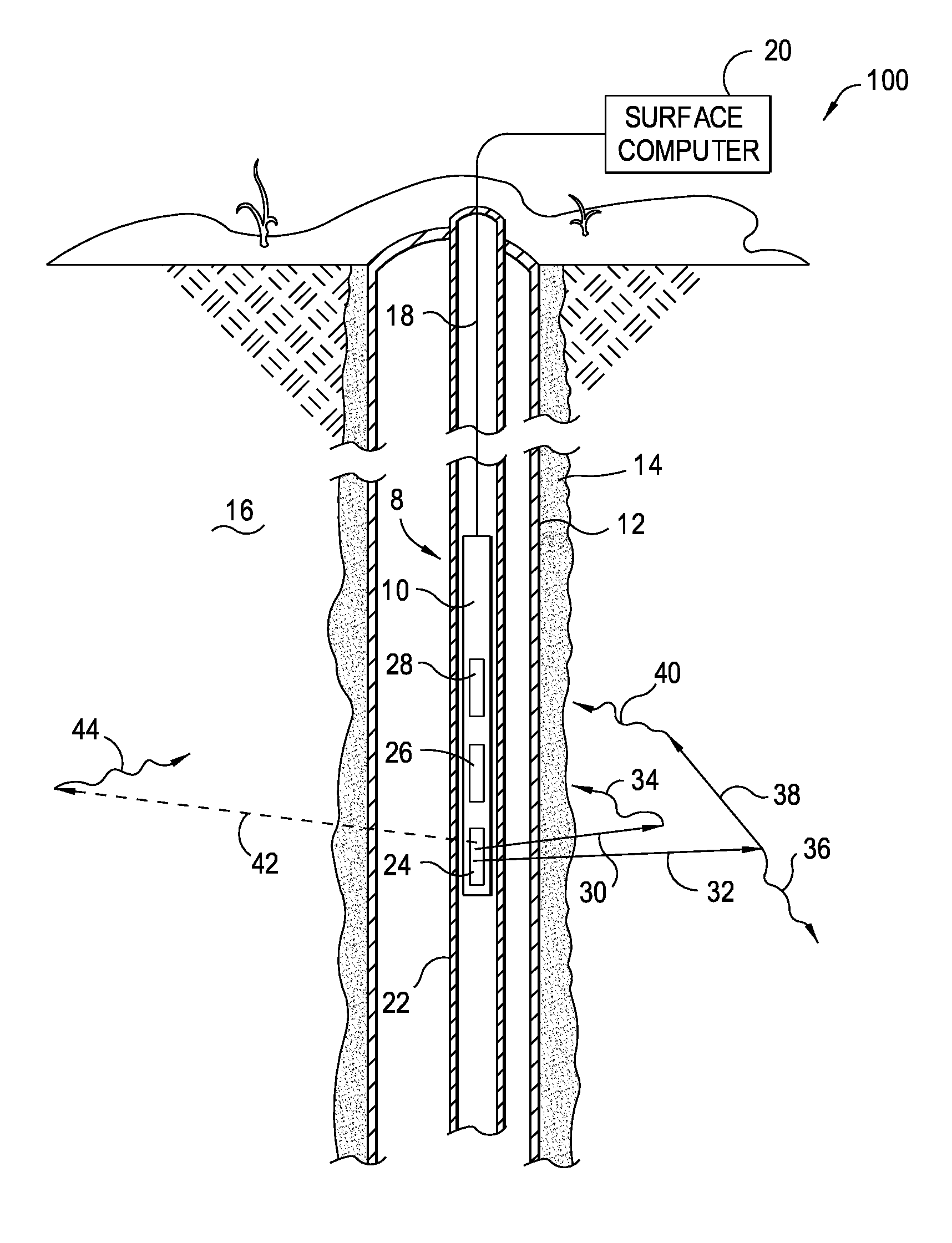
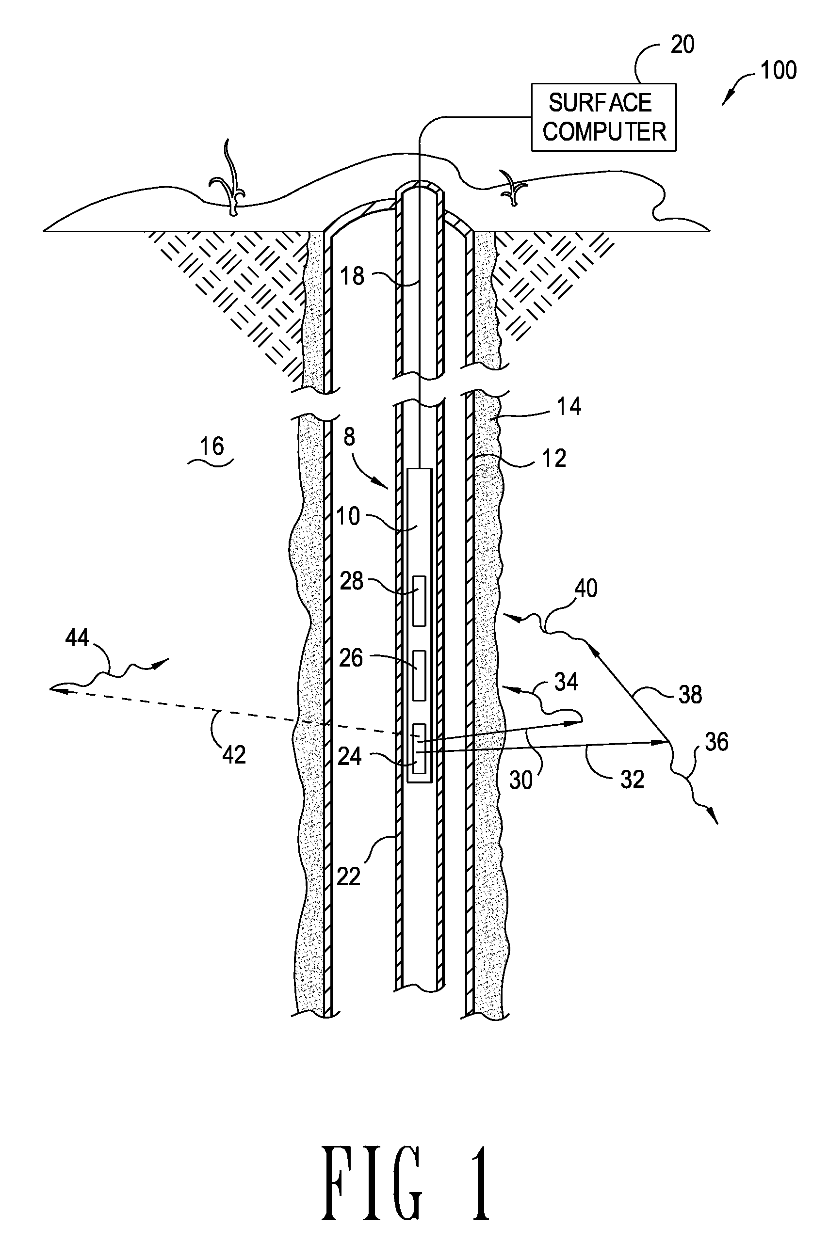
[0022]FIG. 1 illustrates a logging system constructed in accordance with at least some embodiments of the invention. In particular, a logging tool 8 may comprise a tool body or sonde 10, placed within a well casing 12 of a borehole. The well casing 12 may have cement 14 between its outer diameter and the formation 16, and the borehole may be referred to as a cased borehole. While some embodiments of the invention are directed to systems for making bulk density measurements (hereinafter just “density”) in cased boreholes, the description in relation to a cased borehole should not be construed as limiting the embodiments of the invention to only systems operating in a cased borehole environment. The sonde 10 may be suspended within the borehole by an armored multi-conductor cable 18. The cable 18 may not only provide support for the sonde 10, but also may couple a surface computer 20 to various gamma ray detectors and neutron sources (discussed more fully below). The sonde 10 may also...


PUM


Abstract

A method and related system of determining formation density by compensating actual inelastic gamma rays detected from a pulsed-neutron tool for the effects of neutron transport. The method and systems may model response of the tool and use the modeled response as an indication of an amount to compensate detected inelastic gamma rays.

Description

CROSS-REFERENCE TO RELATED APPLICATIONS[0001]This specification is a continuation-in-part of application Ser. No. 10 / 671,351, filed Sep. 25, 2003, titled “Pulsed-Neutron Formation Density”, now U.S. Pat. No. 7,117,092, which application is incorporated by reference herein as if reproduced in full below.BACKGROUND OF THE INVENTION[0002]1. Field of the Invention[0003]Embodiments of the invention are directed to pulsed-neutron density logging tools. More particularly, embodiments of the invention are directed to pulsed-neutron density logging tools that compensate for neutron transport effects.[0004]2. Background of the Invention[0005]Pulsed-neutron logging tools may be used in cased boreholes, and in some situations pulsed-neutron logging tools may be operated within production tubing. Pulsed-neutron logging tools operate on the principle of releasing high energy neutrons, on the order of 14 Mega electron Volts (MeV) into the formation. The high energy neutrons inelastically collide w...

Claims


Application Information

Patent Timeline
Patent Type & Authority Patents(United States)
IPC IPC(8): G01V1/40E21B47/00G01V5/10
CPCG01V5/101
Inventor JACOBSON, LARRY A
Owner HALLIBURTON ENERGY SERVICES INC
Why Eureka
Try Eureka