
Dryer for hair shaving device

a hair shaving and hair technology, applied in drying machines, drying chambers/containers, light and heating equipment, etc., can solve the problems of large size difficult to remove hair pieces or facial grease components, etc., and achieve the effect of simple control and cost-effective structur

Inactive Publication Date: 2011-11-08
MATSUSHITA ELECTRIC WORKS LTD
View PDF15 Cites 2 Cited by
  • Summary
  • Abstract
  • Description
  • Claims
  • Application Information

AI Technical Summary

Benefits of technology

"The present invention provides a dryer for hair shaving devices that can sterilize the blade portion through a simple control and cost-effective structure. The dryer includes a casing with a drying space for the blade portion, a heater, and a fan for drying the blade portion. The control unit can control the output power of the heater and the fan to perform the drying and sterilizing operation modes. The heat generated from the drying heater is transferred to the blade portion during the sterilizing operation mode, eliminating the need for a separate sterilization-exclusive member or mechanism. The control unit can heat the blade portion for a predetermined time period and then stop the heater and drive the fan alone in the sterilizing operation mode. The dryer can perform both the drying and sterilizing operation modes by controlling the output powers of the heater and the fan. This eliminates the need for a separate sterilization-exclusive member or mechanism, making it possible to obtain an effect of sterilizing the blade portion through the use of simple control and cost-effective structure."

Problems solved by technology

It is difficult to remove the hair pieces or facial grease components by merely cleaning the blade portion with a brush or the like.
The hair pieces or facial grease components tend to leave an unpleasant smell.
Since the heat generation unit and the protection member are built within the shaver head, however, the conventional electric razor disclosed in Japanese Patent Laid-open Publication No. 2005-199083 has a problem in that the structure thereof becomes complicated and large-sized due to the increase in the number of parts.
However, since the shaver cleaning and drying device is adapted to clean the blade portion and then dry the same by allowing air to flow through the blade portion, various germs or bacteria adhering to a blade surface or blade holes of the blade portion are not sufficiently sterilized but are left alive.
This poses a problem in that it is impossible to keep the blade portion hygienic.

Method used


Image

  • Dryer for hair shaving device
  • Dryer for hair shaving device
  • Dryer for hair shaving device

Examples


Embodiment Construction

[0026]The embodiments of the present invention will be described with reference to the accompanying drawings which form a part hereof.

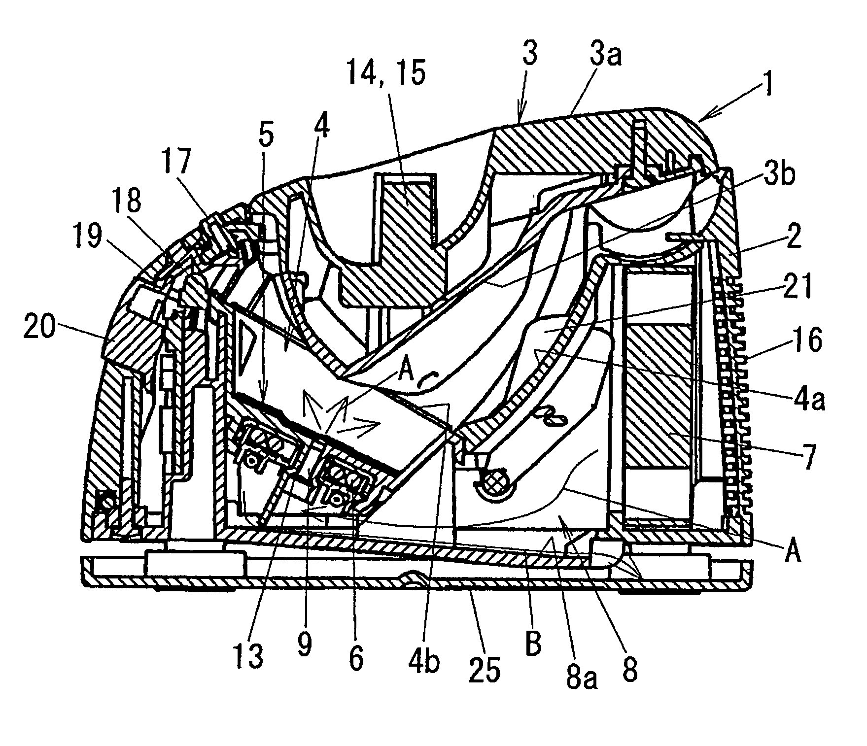
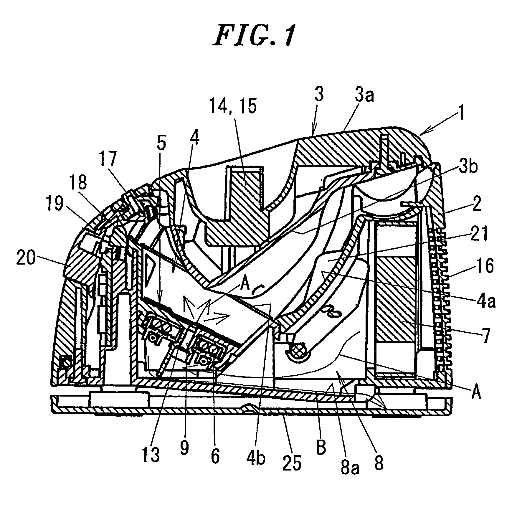
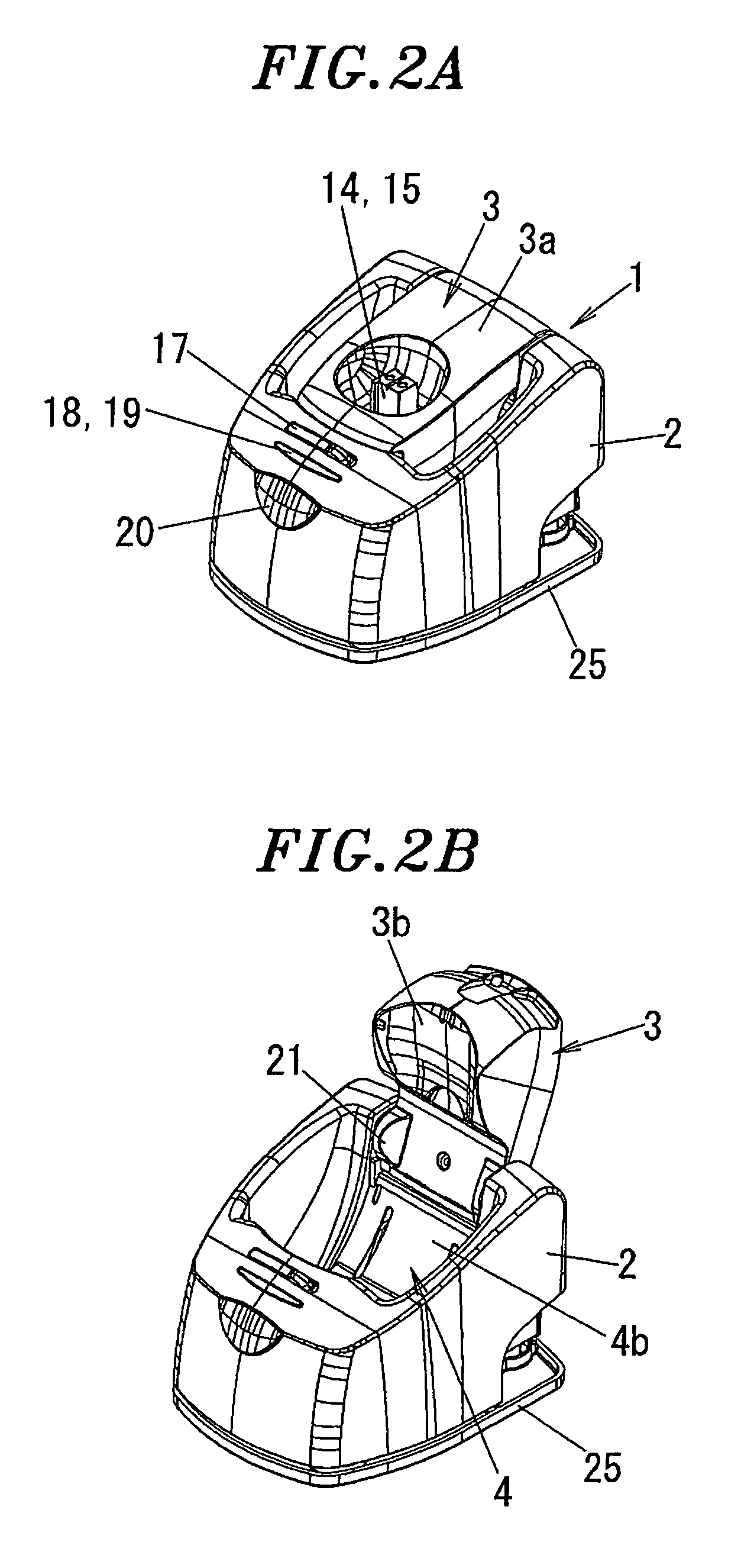
[0027]FIGS. 1 to 3E show a dryer for hair shaving devices 1 in accordance with the present invention (hereinafter referred to as a “dryer 1”). FIGS. 4A and 5 are views illustrating a state that a blade portion 32 of a hair shaving device 30 is inserted into the dryer 1. In the following description, a reciprocating electric razor is cited as an example of the hair shaving device 30.

[0028]The dryer 1 includes a box-shaped casing 2 having a drying space 4 formed inside the casing 2. The drying space 4 communicates at its upper end with an upwardly opened blade portion insertion 4b. The blade portion 32 is removably inserted into the drying space 4 through the blade portion insertion 4b in a downwardly facing state. In a bottom portion of the drying space 4, there is arranged a blade rest tray 5 for receiving the blade portion 32 which will be described ...


PUM


Abstract

A dryer for hair shaving devices includes a casing having a drying space for removably receiving a blade portion of a hair shaving device, and a heater and a fan for drying the blade portion received in the drying space. Also, a control unit is provided for controlling output power of the heater and the fan to perform operation modes, the operation modes include a drying operation mode in which the heater and the fan are driven simultaneously and a sterilizing operation mode in which the heater alone is driven with the fan kept stopped.

Description

FIELD OF THE INVENTION[0001]The present invention relates to a dryer for hair shaving devices and, more specifically, to a dryer for hair shaving devices capable of sterilizing a blade portion of a hair shaving device and keeping the same in a hygienic state.BACKGROUND OF THE INVENTION[0002]Hair pieces or facial grease components are apt to adhere to a blade portion of an electric razor, which is one of hair shaving devices. It is difficult to remove the hair pieces or facial grease components by merely cleaning the blade portion with a brush or the like. The hair pieces or facial grease components tend to leave an unpleasant smell.[0003]In view of this, there is conventionally known an electric razor including a shaver head, a heat generation unit arranged within the shaver head for generating heat for a drying purpose and a protection member received within the shaver head for covering and protecting a blade portion, wherein the blade portion is dried by the heat generated from th...

Claims


Application Information

Patent Timeline
Patent Type & Authority Patents(United States)
IPC IPC(8): F26B19/00B26B19/38F26B25/06
CPCA45D27/48B26B19/38B26B19/00
Inventor UEDA, YASUNORIKASHIWABARA, MINORUIBUKI, YASUO
Owner MATSUSHITA ELECTRIC WORKS LTD
Learn More