
Water cooling type heat dissipation module for electronic device

a technology of heat dissipation module and electronic device, which is applied in the direction of positive displacement liquid engine, pump, lighting and heating apparatus, etc., can solve the problems of inability to immediately transfer heat received by the base to the top of the cooling fin, and the heat generated by the central processing unit in the recent years cannot be dissipated with the cooling fin, so as to achieve the effect of rapid removal of heat from the heat generating component and faster circulation of cooling water

Inactive Publication Date: 2011-11-08
ASIA VITAL COMPONENTS SHENZHEN CO LTD
View PDF3 Cites 38 Cited by
  • Summary
  • Abstract
  • Description
  • Claims
  • Application Information

AI Technical Summary

Benefits of technology

[0007]In order to overcome the deficiencies of the preceding prior art, an object of the present invention is to provide a water cooling type heat dissipation module for an electronic device, which is capable of removing heat of the heat generating component rapidly and providing faster circulation of cooling water.

Problems solved by technology

It is inevitable that a great deal of amount of heat is generated during the electronic component is in operation.
However, heat generated from the central processing unit developed in the recent years is unable to be dissipated with the cooling fins only and a fan for removing heat becomes a required device in addition to the cooling fins.
Because there is a distance between the base of the cooling fins and the fan, the heat received by the base is incapable of transmitting to the tops of the cooling fins immediately.
As a result, most of the heat accumulates at the base to deteriorate efficiency of heat dissipation.
However, the heat generating component such as the central processing unit contacts with the cooling fins directly instead of the guide heat pipes such that the heat received with the cooling fins are still incapable of being directly dissipated effectively.

Method used


Image

  • Water cooling type heat dissipation module for electronic device
  • Water cooling type heat dissipation module for electronic device
  • Water cooling type heat dissipation module for electronic device

Examples


Embodiment Construction

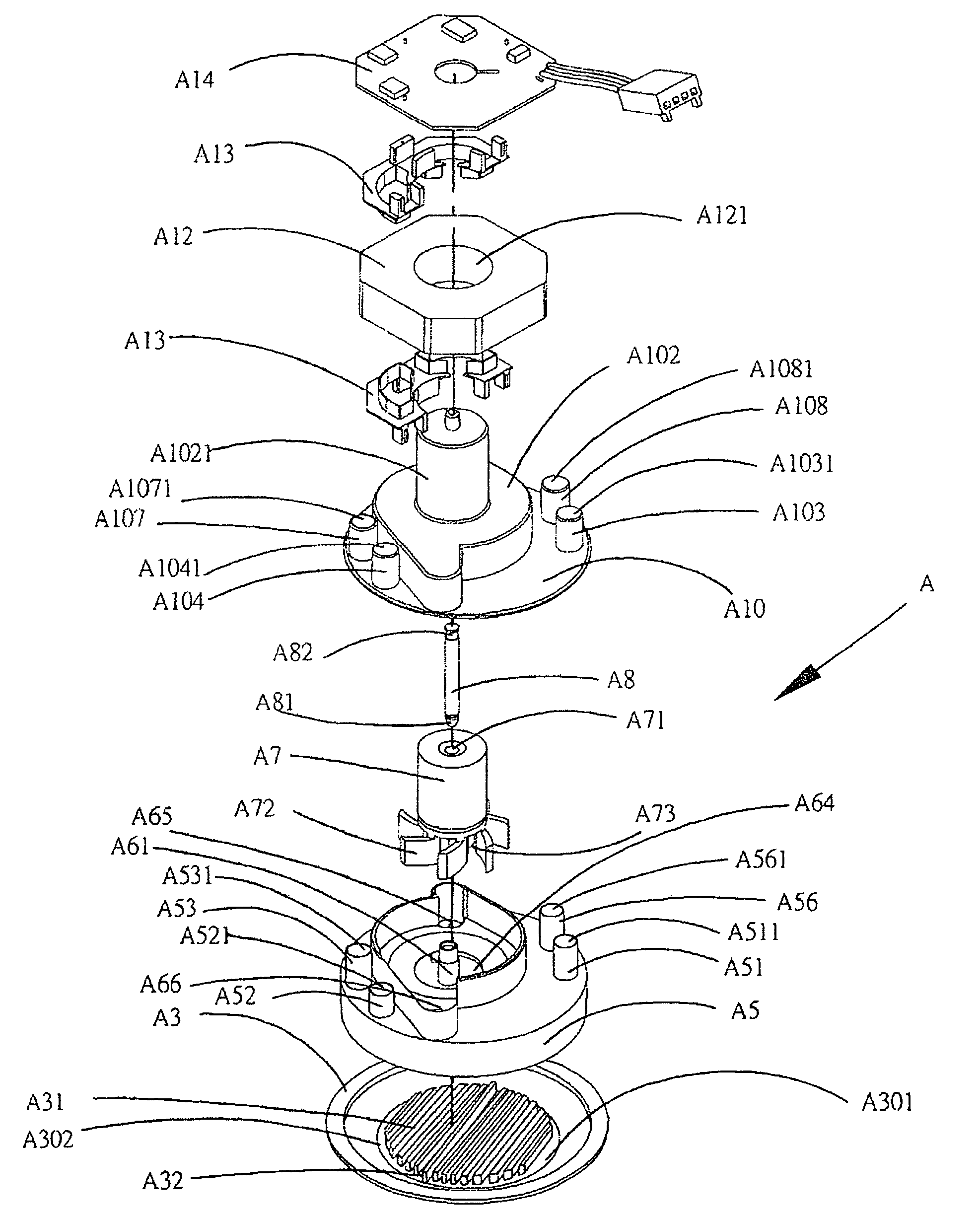
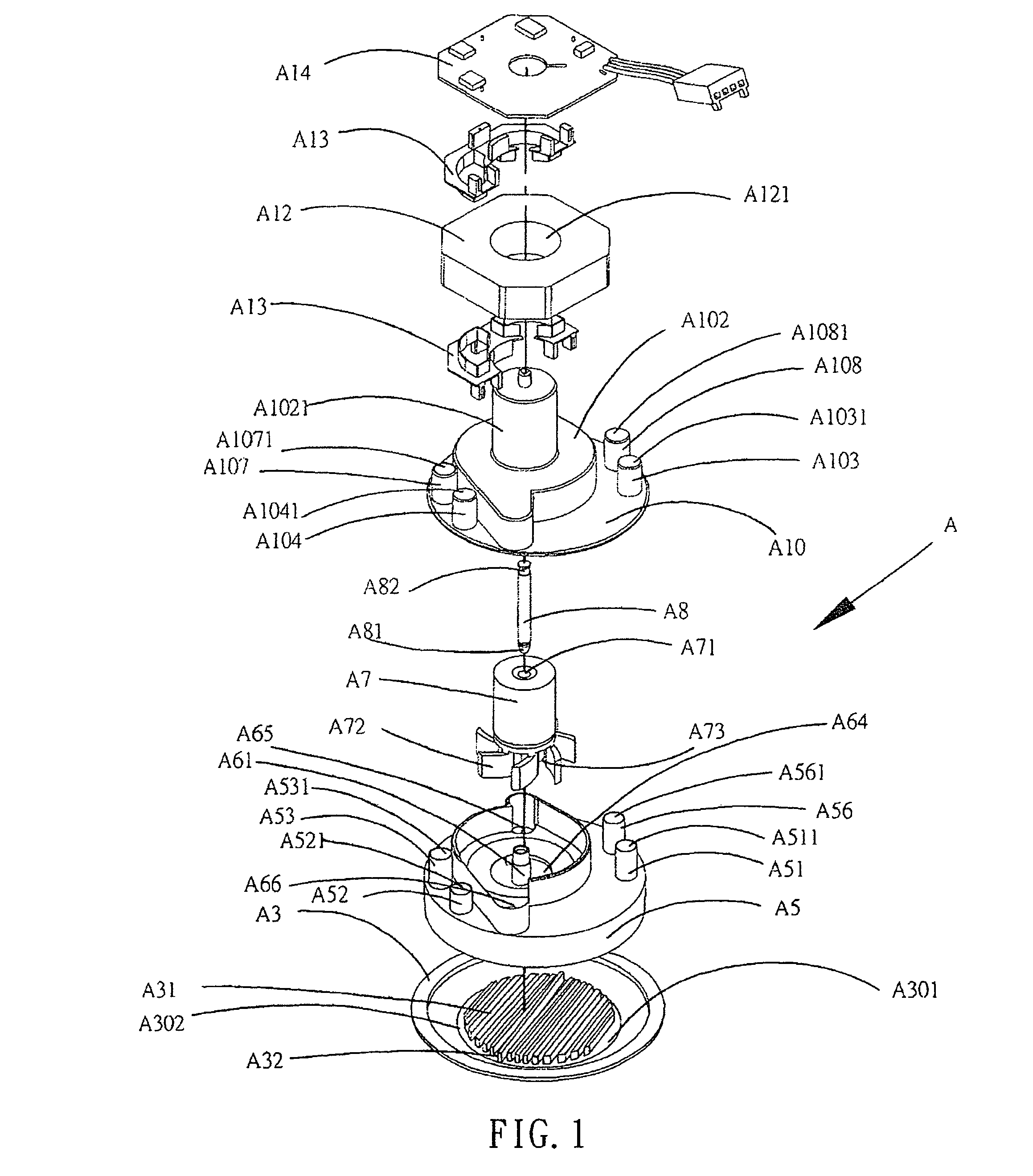
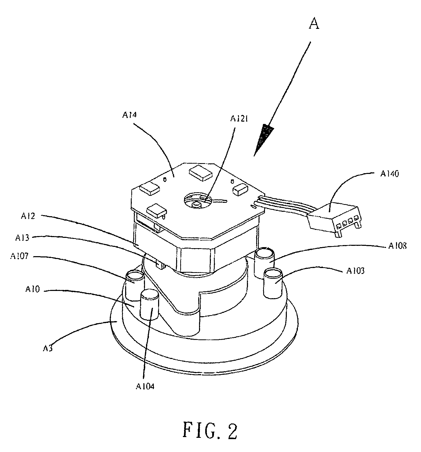
[0018]Referring to FIG. 1, the preferred embodiment of a water cooling type heat dissipation module according to the present invention includes a suction disk A5, a base disk A3, a water guide A6, a guide fan A7, a spindle A8, a cover A10, a motor A12, a motor seat A13 and a printed circuit (PC) board A14.

[0019]Wherein, the base disk A3 has a containing space A30 and a plurality of cooling strips A31. Further, a baffle fin A32 is provided at the middle of containing space A30 among the cooling strips A3 for separating the containing space A30 into two independent containing space sections while the suction disk A5 is attached to the base disk A3; the suction disk A5 is disposed on top of the base disk and provides a first and second inlets A51, A53 and a first and second outlets A52, A56, wherein the first inlet A51 is disposed to be diagonally opposite to the second inlet, and the first outlet A52 is disposed to be diagonally opposite to the second outlet A56. The water guide A6 is...


PUM

PropertyMeasurementUnit
food propertyaaaaaaaaaa
heat dissipation moduleaaaaaaaaaa
temperatureaaaaaaaaaa

Abstract

A water cooling type heat dissipation module for an electronic device includes a base disk, a suction disk, a water guide and a cover. The base has two containing spaces and a plurality of cooling strips in the containing space. The suction base is attached to the base disk and further includes two water chambers for receiving sucked water, two inlets and two outlets. The water guide is attached to the suction disk with two guide port at the periphery thereof. The cover closes the suction disk and is movably joined to a guide fan. When the heat dissipation module is full with fluid, the fluid can flow therein rapidly while the guide fan rotating such that the fluid is discharged from and flows into the heat dissipation module more effectively.

Description

BACKGROUND OF THE INVENTION[0001]1. Field of the Invention[0002]The present invention is related to a water cooling type heat dissipation module and particularly to a heat dissipation module with which a guide fan is associated for speeding up circulation of cooling water to enhance efficiency of heat exchange.[0003]2. Brief Description of the Related Art[0004]Many electric circuits being formed as electronic components or electronic circuits being formed of a plurality of integrated circuits joining to each other that were developed in the early stages have more and more been replaced with a comfortable integrated circuit due to growing technology of the integrated circuit and progressive manufacturing process of the semiconductor. That is, an integrated circuit is capable of performing more functions and is capable of processing more complicated instructions and signals. It is inevitable that a great deal of amount of heat is generated during the electronic component is in operati...

Claims


Application Information

Patent Timeline
Patent Type & Authority Patents(United States)
IPC IPC(8): F28F7/00H05K7/20B29C47/88F28D15/00F04B23/00F04B35/04
CPCH01L23/473H01L2924/0002H01L2924/00
Inventor CHIANG, KUEI-FUNG
Owner ASIA VITAL COMPONENTS SHENZHEN CO LTD
Learn More