Soil treatment apparatus

a technology of soil treatment and equipment, which is applied in the direction of soil-working equipment, lawn mowers, tilling equipment, etc., can solve the problems of unsuitable construction for higher speeds, no well-defined plunging angle, and drawbacks of abrasion wear, etc., and achieve the effect of higher speeds

Inactive Publication Date: 2011-11-08
WIEDENMANN GMBH
View PDF37 Cites 12 Cited by
  • Summary
  • Abstract
  • Description
  • Claims
  • Application Information

AI Technical Summary

Benefits of technology

[0016]The invention makes use of the idea that, to further increase the speed, the time taken to return the plunger tool to the stop must be kept as short as possible. As a result, with increased operating speeds, counteraction against the centrifugal force is also increased, which also means that the biasing device must be dimensioned correspondingly larger. This increases the moved masses, which in turn prevents a possible acceleration of the operating speed.
[0051]a hollow tine operation can be improved, since pivoting is reduced in the plunging stroke and therefore an ejection channel of the tine is no longer blocked by compressed matter.

Problems solved by technology

This construction entails that the plunger tools rub along the stop common to all plunger tools, which is a drawback with respect to abrasive wear.
Moreover, no well-defined plunging angle is achievable with such a construction; plunging is always carried out only with the plunger tools sliding on the stop beam, so that the plunging angle depends on the bracket position and the distance from the soil.
This construction is unsuitable for higher speeds, since there is a risk that the brackets are no longer guided on the eccentric disk, at least intermittently, but flung off from the latter.
In the context of the plunging function, this entails the risk of extremely hard knocks on the eccentric shaft, which makes faster operation impossible.

Method used


Image

  • Soil treatment apparatus
  • Soil treatment apparatus
  • Soil treatment apparatus

Examples


first embodiment

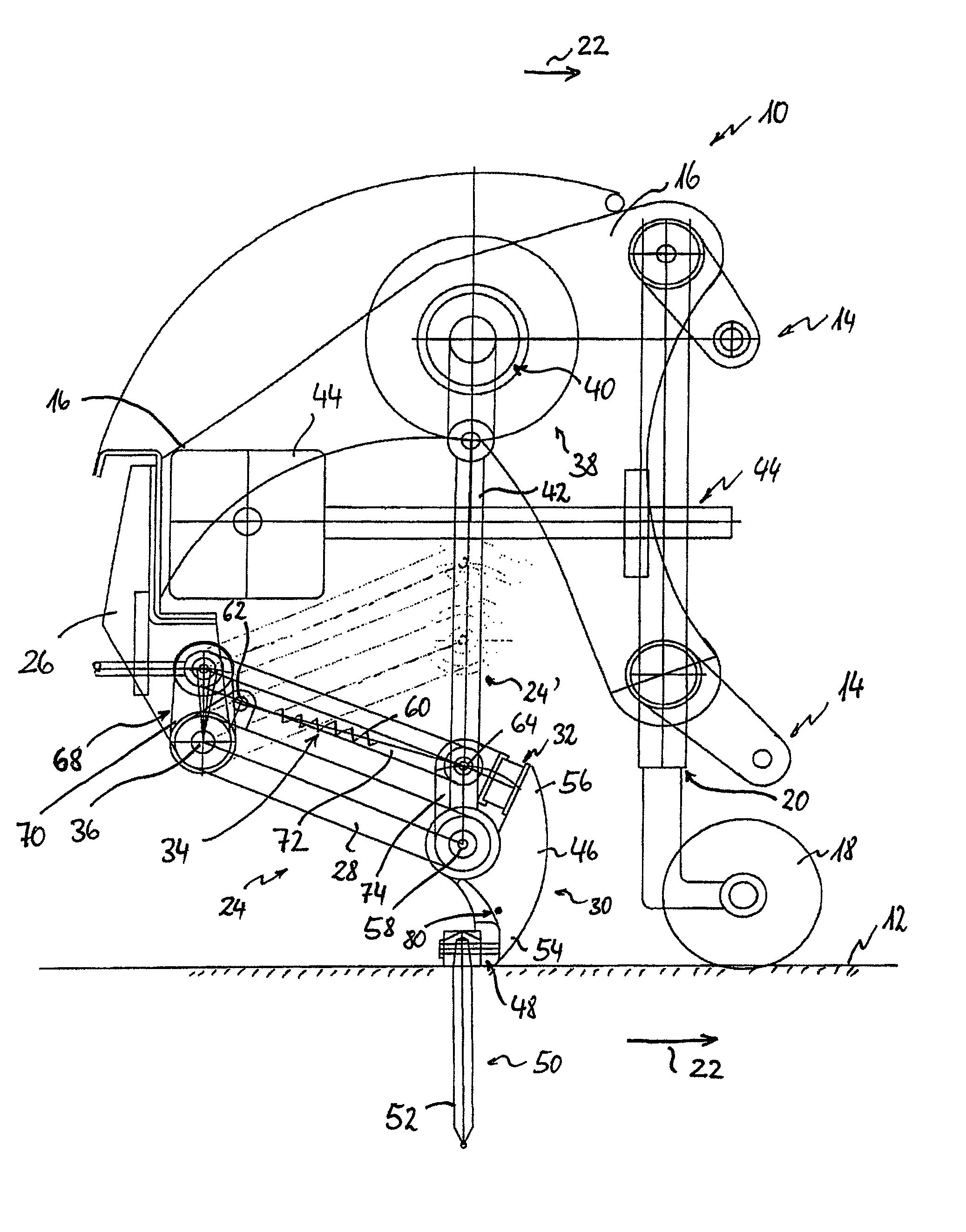
[0062]FIG. 1 shows a side view of a soil treatment apparatus 10. The soil treatment apparatus is driveable across soil 12. In the embodiment shown in FIG. 1 soil treatment apparatus 10 is linkable to a traction vehicle, such as a tractor (not shown) by means of ordinary linking means 14. Soil treatment apparatus 10 has a machine frame or chassis 16 on which linkage means 14 are attached. Chassis 16 is supported on soil 12 by a soil roller 18. Soil roller 18 is mounted on chassis 16 via a height adjustment device 20.

[0063]Arrow 22 shows the driving direction (forward driving direction). Driving direction 22 is from left to right in the view of FIG. 1. Transverse to driving direction 22, there is a row of a plurality of tool units 24 linked to chassis 16. Of tool units 24, only a first tool unit 24 is shown because of the lateral view and for better clarity. First tool unit 24 is shown in a fully lowered position. The broken lines schematically show a second tool unit 24′ in a fully r...

second embodiment

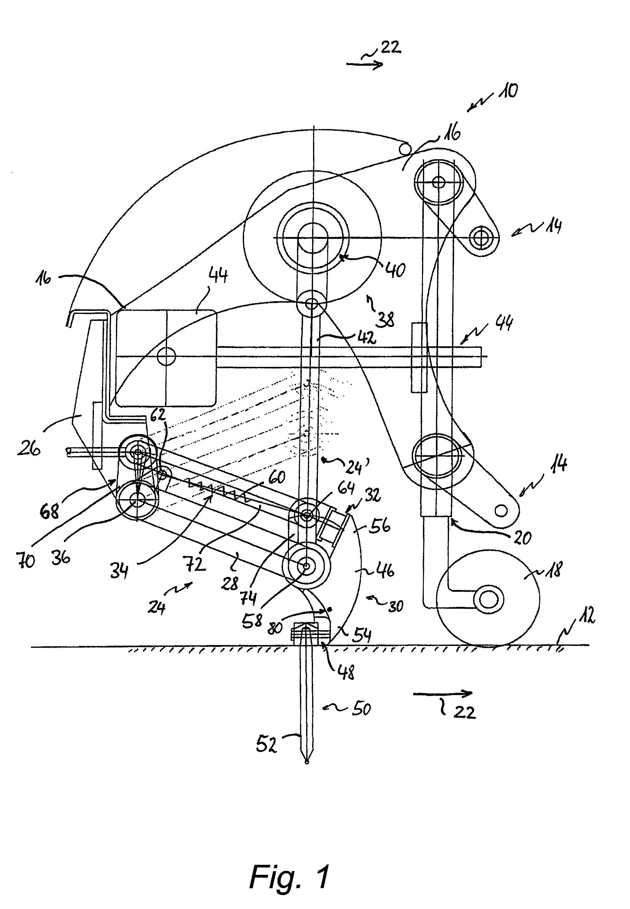
[0070]The above mentioned second attachment point 64 of biasing device 34 is formed on a lateral attachment of second lever arm 56 (hidden in the drawings and therefore not shown) in such a way that it coaxially coincides with the linkage of guiding rod 72 on pivoting element 74. A comparable tool unit 24 with plunger tool device 30 and stop 32 is individually shown again for illustration. Tool unit 24 of FIG. 2 is part of the soil treatment apparatus distinguished from the embodiment shown in FIG. 1 only in that angular position adjustment device 68 is not a central adjustment element 70 but comprises individual angular adjustment device 86 present separately per each tool unit 24 on an individual basis for individually adjusting stop 32 of each tool unit 24.

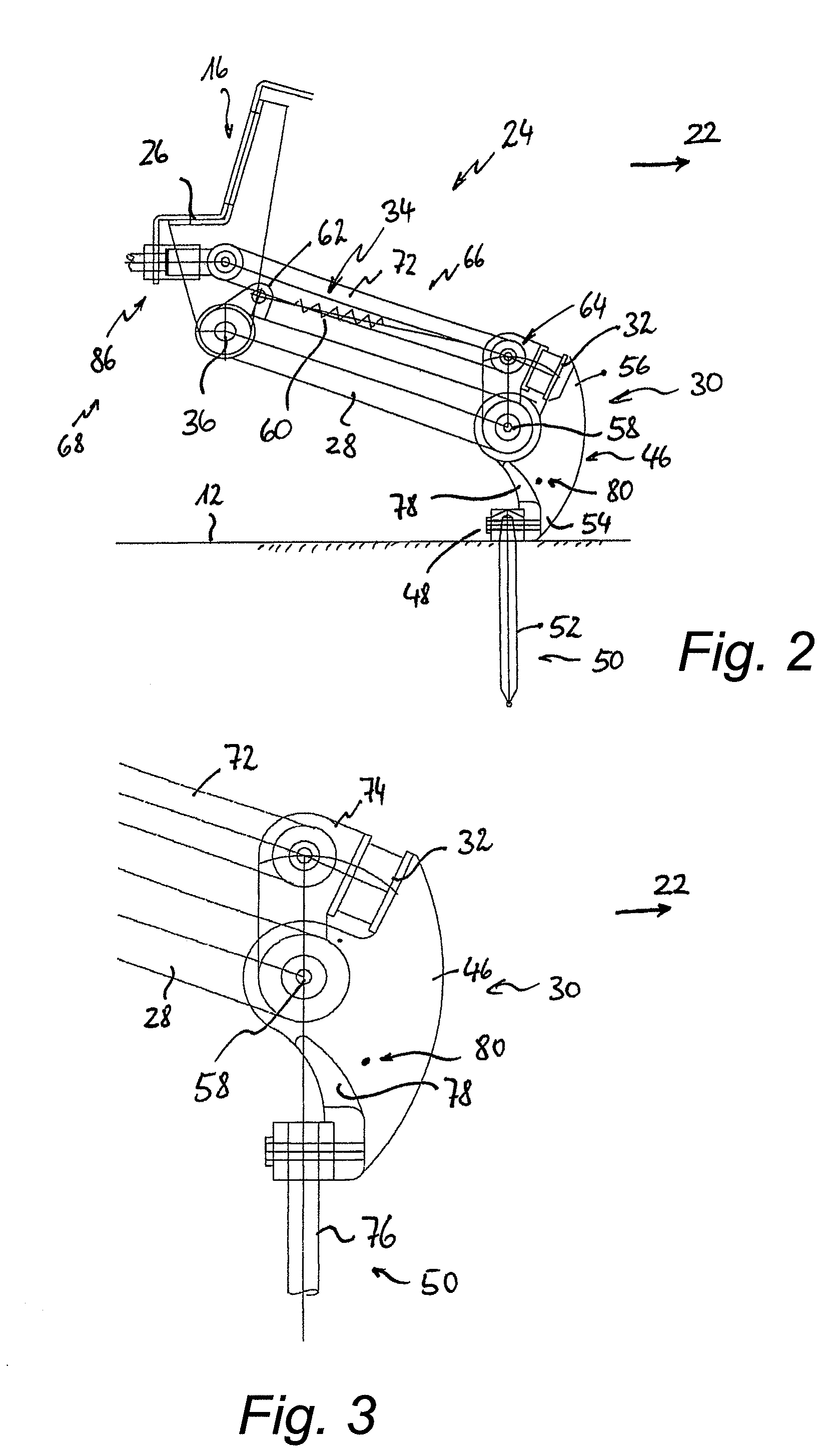
[0071]FIG. 3 shows the front free end section of tool unit 24 with lever element 46 and stop 32 on pivoting element 74. As a plunger tool 50, a hollow tine or hollow spoon 76 is attached here on plunger tool holder 48. Above pl...


PUM


Abstract

A soil treatment apparatus has a plurality of tool units that have at least one bracket, at least one plunger tool and at least one stop for the plunger tool. The bracket with an end section on a chassis is driven up and down to pivot about a first pivoting axis. The plunger tool device is linked at another end section of the bracket to pivot about a second pivoting axis. The stop is formed such that plunging is carried out at a predefined plunging angle. To enable faster operating speeds, the first pivoting axis is provided behind the second pivoting axis as seen in a driving direction, and the plunger tool device is linked such that whenever the bracket is pivoted about the first pivoting axis it is subjected to a centrifugal force in a direction toward a position limited by the stop.

Description

CROSS-REFERENCE TO RELATED APPLICATIONS[0001]This application claims priority under 35 U.S.C. §119 to German Patent Application No. 10 2008 013 350.7, filed Mar. 10, 2008, and German Patent Application No. 10 2008 017 242.1, filed Apr. 4, 2008. The entire disclosures of German Patent Application Nos. No. 10 2008 013 350.7 and 10 2008 017 242.1 are hereby incorporated herein by reference.BACKGROUND OF THE INVENTION[0002]1. Field of the Invention[0003]This invention generally relates to a soil treatment apparatus. More specifically, the present invention relates to a soil treatment apparatus traversable across the soil in a driving direction.[0004]2. Background Information[0005]A soil treatment apparatus is traversable across the soil in a driving direction. This can be realized, for example, by configuring the soil treatment apparatus for linkage mounting on a tractor, or to form it as an automotive unit, or even as a push unit for pushing from behind or as a pull unit for pulling in...

Claims


Application Information

Patent Timeline
Patent Type & Authority Patents(United States)
IPC IPC(8): A01B45/02
CPCA01B45/023
Inventor WIEDENMANN, GEORG
Owner WIEDENMANN GMBH
Why Eureka
Try Eureka