Device with removable projections

a technology of projections and devices, applied in the field of devices with removable projections, can solve the problems of difficult delivery of devices, inability to properly position devices at the desired site, and high cost of insertion, and achieve the effect of promoting the ingress of devices

Active Publication Date: 2011-11-08
COOK MEDICAL TECH LLC +1
View PDF9 Cites 11 Cited by
  • Summary
  • Abstract
  • Description
  • Claims
  • Application Information

AI Technical Summary

Benefits of technology

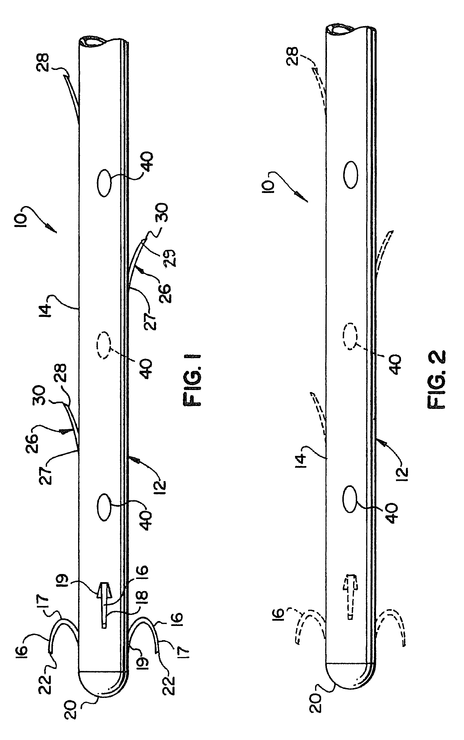
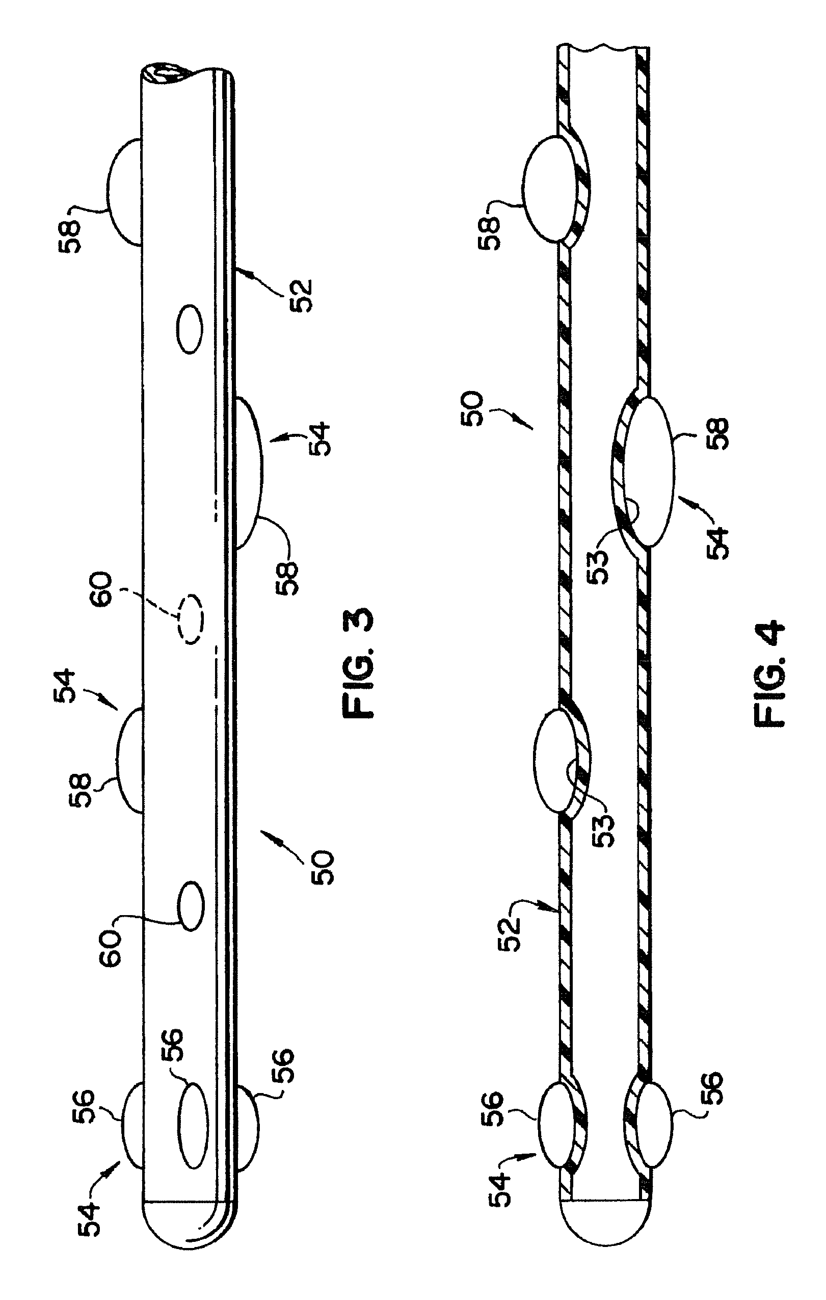
[0012]In still another form thereof, the invention comprises a medical device configured for dynamic movement through a body canal toward an interior target site and removal therefrom. The device includes an elongate tubular member having a plurality of distal projections disposed on an exterior surface thereof. The projections extend radially outwardly from the exterior surface of the tubular member a distance sufficient to engage an interior surface of the body canal during bodily contractions therein. The distal projections are configured so as to promote ingress of the device in response to the contractions. At least some of the projections are removable from the elongate tubular member under bodily conditions at the body canal for facilitating removal of the feeding device from the target site.

Problems solved by technology

However, the devices were often difficult to deliver and properly position at the desired site.
In addition, insertion required a good deal of physician time and effort to insure adequate placement.
Although the flaps are generally flexible, the presence of such flaps is unnecessary when the tube is withdrawn, and the additional diameter occupied by the flaps may impose an impediment to withdrawal.

Method used


Image

  • Device with removable projections
  • Device with removable projections
  • Device with removable projections

Examples


Embodiment Construction

[0017]For purposes of promoting an understanding of the present invention, reference will now be made to the embodiments illustrated in the drawings, and specific language will be used to describe the same. It should nevertheless be understood that no limitation of the scope of the invention is thereby intended, such alterations and further modifications in the illustrated device, and such further applications of the principles of the invention as illustrated therein being contemplated as would normally occur to one skilled in the art to which the invention relates.

[0018]In the following discussion, the terms “proximal” and “distal” will be used to describe the opposing axial ends of the inventive device, as well as the axial ends of various component features of the device. The term “proximal” is used in its conventional sense to refer to the end of the device (or component thereof) that is closest to the operator during use of the device. The term “distal” is used in its conventio...


PUM


Abstract

A feeding device configured for insertion into the gastrointestinal tract of a patient, and dynamic movement through the gastrointestinal tract toward the jejunum. The device includes an elongate tubular member having a plurality of distal projections disposed on an exterior surface thereof. The projections extend radially outwardly from the exterior surface of the tubular member a distance sufficient to engage an interior surface of the gastrointestinal tract during peristaltic contractions therein, and are configured to promote ingress of the device in response to the contractions. At least some of the projections are soluble under bodily conditions at the gastrointestinal tract, thereby facilitating removal of the feeding device.

Description

RELATED APPLICATION[0001]The present patent document claims the benefit of the filing date under 35 U.S.C. §119(e) of Provisional U.S. Patent Application Ser. No. 60 / 926,862, filed Apr. 30, 2007, which is hereby incorporated by reference.BACKGROUND OF THE INVENTION[0002]1. Technical Field[0003]The present invention relates to a device for invading body canals non-destructively and with a minimum of trauma. More particularly, the invention relates to a device, such as a feeding tube, having one or more removable external projections for dynamic advancement of the distal end of the device to the desired body site.[0004]2. Background Information[0005]Medical devices intended for non-destructive invasion of body canals have typically been provided with a low friction external surface. The low friction surface has a slippery texture to facilitate ingress of the device into the body canal for carrying out a medical procedure, and egress of the device from the body canal following terminat...

Claims


Application Information

Patent Timeline
Patent Type & Authority Patents(United States)
IPC IPC(8): A61M5/32
CPCA61J15/003A61J15/0003A61J15/0069A61M2025/0096
Inventor YOUNG, RONAN T.HIATT, MARK J.HOFFA, ANDREW K.
Owner COOK MEDICAL TECH LLC
Why Eureka
Try Eureka