
Cut-off acetabular reamer

a technology of acetabular reamer and cutting edge, which is applied in the field of surgical products, can solve the problems of additional challenges for medical instruments and implants, and break through this thin floor, and achieve the effect of optimizing surgeon visibility and avoiding break-through and destruction of the medial wall

Active Publication Date: 2011-11-08
VIANT AS&O HLDG LLC
View PDF12 Cites 23 Cited by
  • Summary
  • Abstract
  • Description
  • Claims
  • Application Information

AI Technical Summary

Benefits of technology

[0011]An acetabular reamer is intended in particular for the shaping of the cotyloid cavity in the event of a replacement of a hip joint by total prosthesis. The reamer is typically of a truncated hemispherical form and is adapted for attachment to a reamer spindle in order to be driven in rotation about a cutter axis. Consequently, it is no longer necessary to cut a full, continuous hemisphere up to the apex of the hemispherical body, thereby attaining the principal advantage of the invention, namely, to adequately prepare the acetabulum for receipt of a prosthesis while minimizing the possibility of breakthrough of the fovea / acetabular fossa. The reamer has an interface typically made up of cross bars which a holder engages for rotationally activating the reamer for cutting.
[0012]An object of the invention is to preserve bone via minimal resection of the acetabulum—in this manner, the floor of the acetabulum is not destroyed so avoiding break-through and destruction of the medial wall during reaming.
[0013]A further object is to optimize a surgeon's visibility during the reaming process.

Problems solved by technology

Meeting this additional requirement provides an additional challenge to the designers of medical instruments and implants.
Minimal resection is particularly applicable to the acetabulum as it has a paper-thin translucent floor which can sometimes be damaged when using a conventional hemispherical reamer, given that sweeping using a conventional reamer cannot be avoided, and so the full hemispherical shape of the sweep can sometimes break through this thin floor.

Method used


Image

  • Cut-off acetabular reamer
  • Cut-off acetabular reamer
  • Cut-off acetabular reamer

Examples


Embodiment Construction

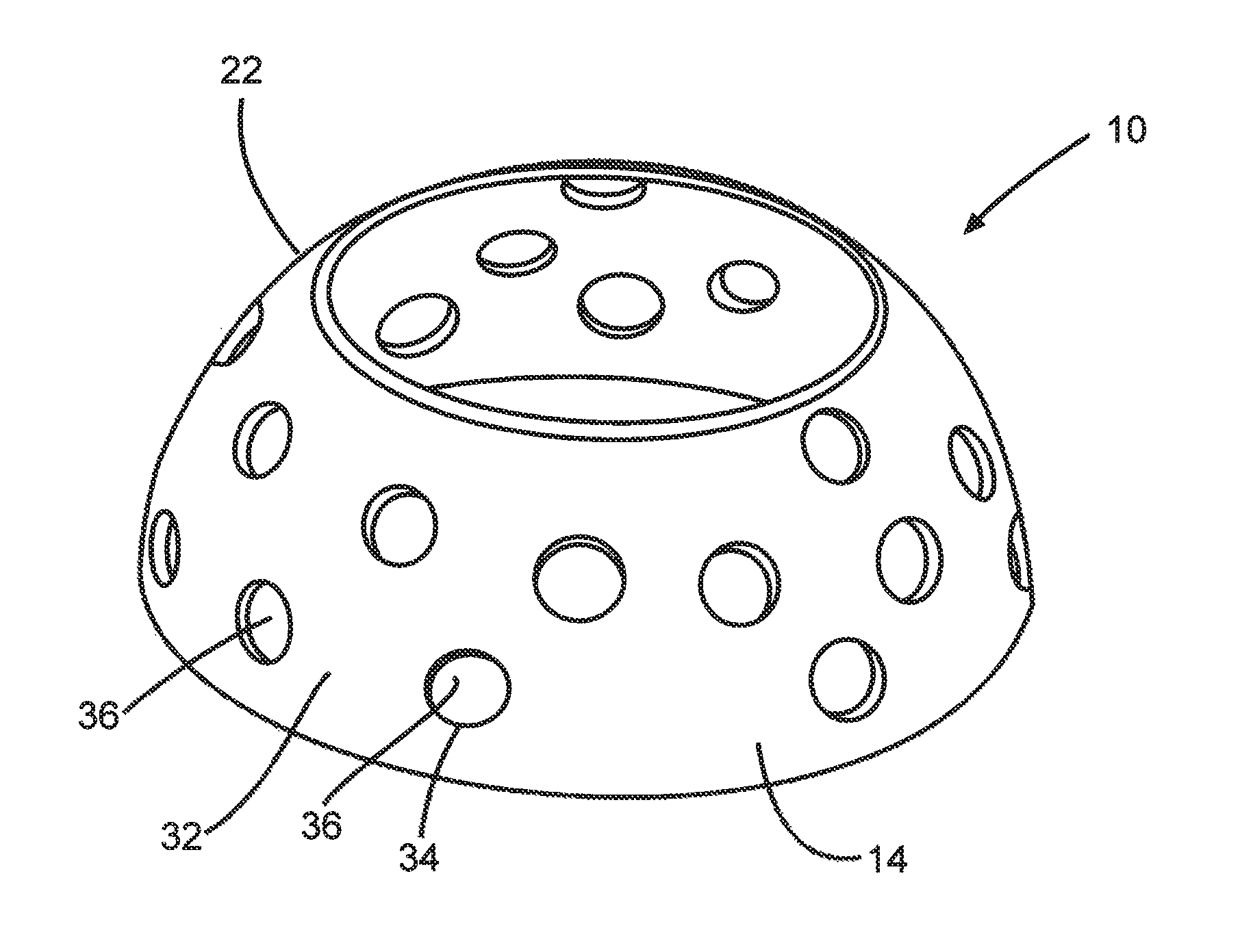
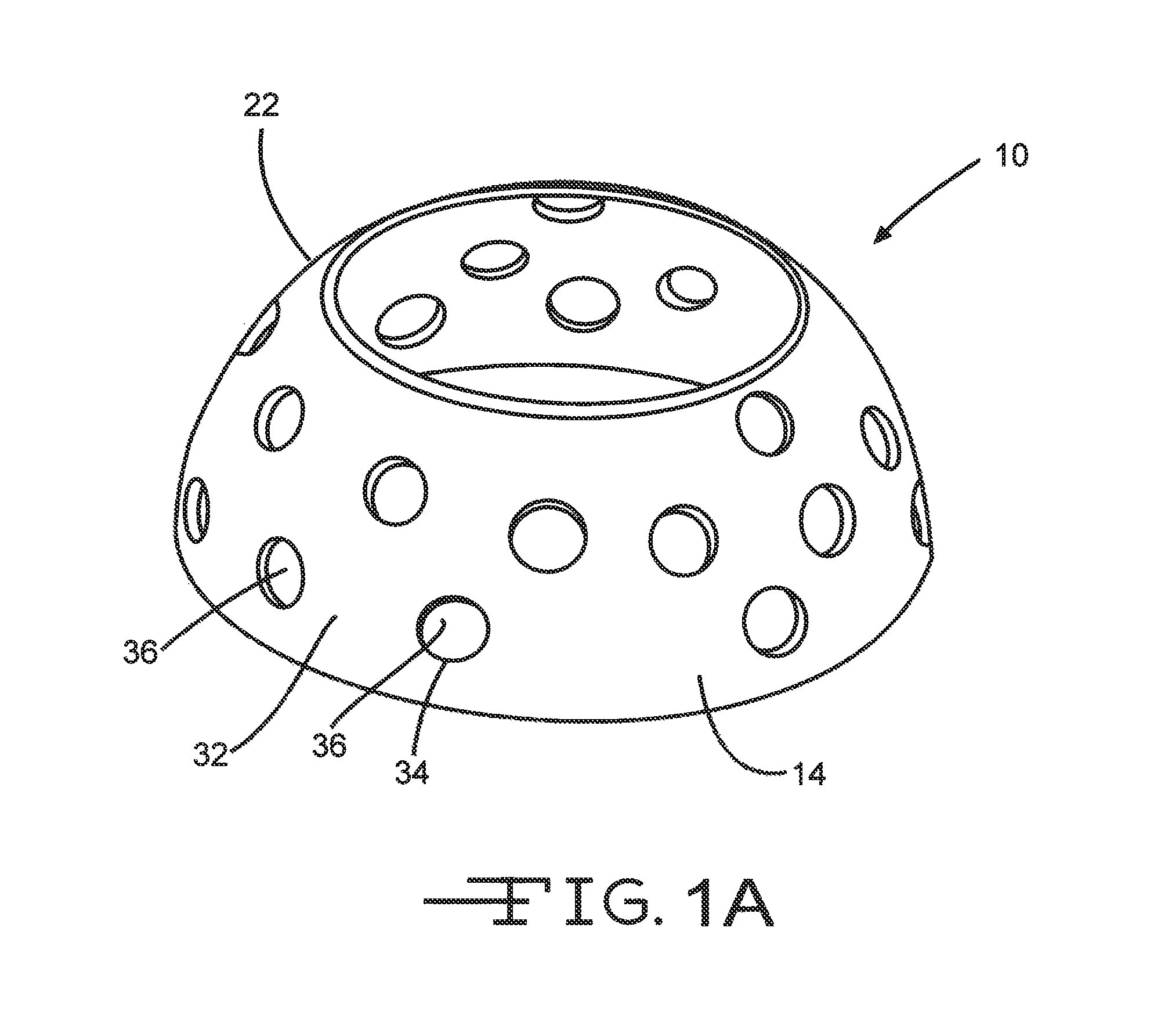
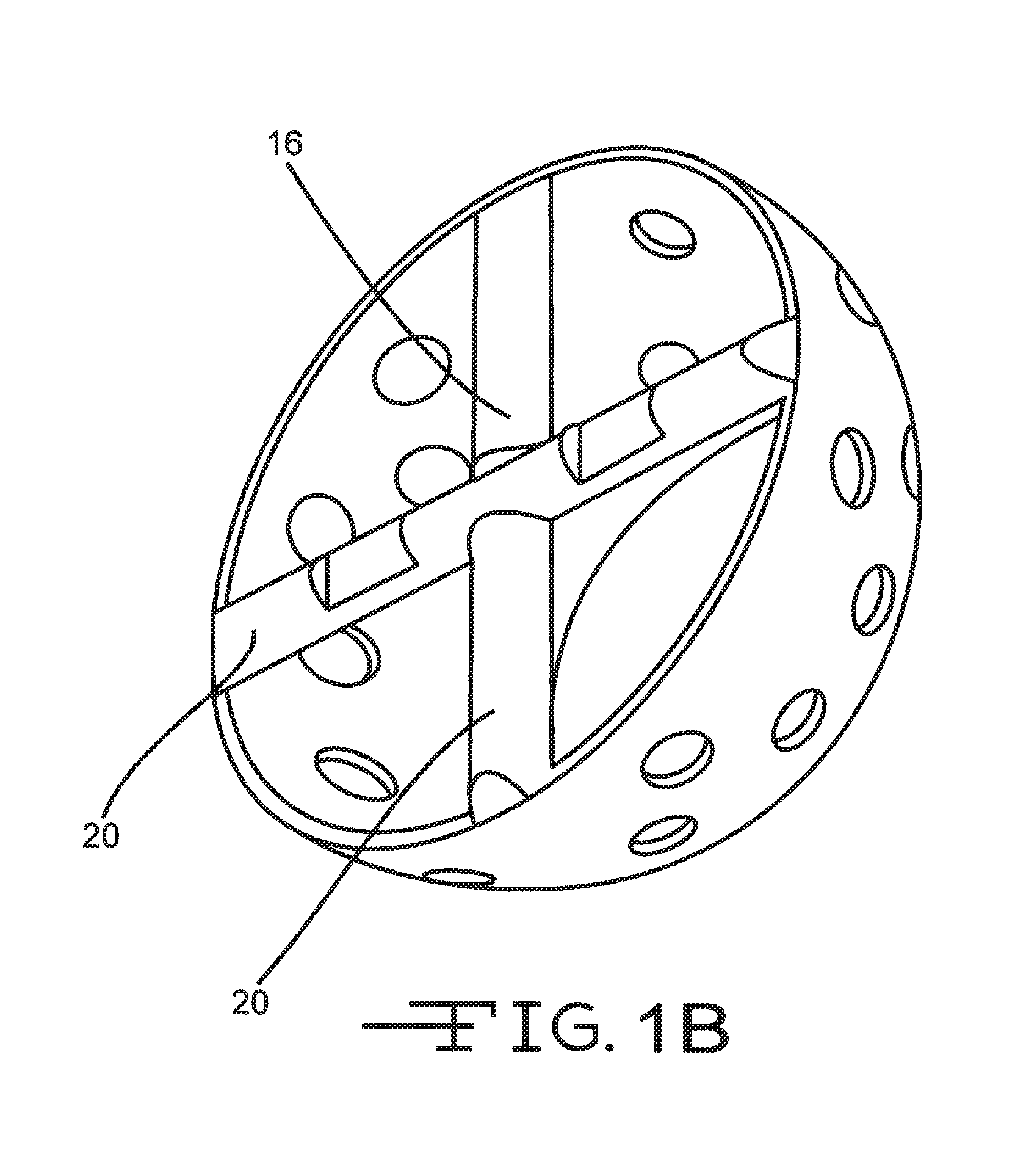
[0031]Referring now to FIG. 1A, the reamer 10 of the invention is an acetabular reamer intended in particular for the shaping of the cotyloid cavity in the event of a replacement of a hip joint by total prosthesis. The reamer 10 is typically of a truncated hemispherical form and is adapted for attachment to a reamer spindle in order to be driven in rotation about a cutter axis 11. The necessity to cut a full, continuous hemisphere to the apex 12 of the hemispherical body 14 is suppressed, so as to attain the principal advantage of the invention, namely, to adequately prepare the acetabulum for receipt of prosthesis while minimizing the possibility of breakthrough of the fovea / acetabular fossa (the paper-thin translucent floor of the acetabulum). The reamer 10 has an interface 16 typically comprising cross bars 20, which a holder (not shown) engages for rotationally activating the reamer for cutting. A reamer of the prior art is described in U.S. patent application Ser. No. 10 / 208,85...


PUM


Abstract

An acetabular reamer (10, 10′, 10″) is intended in particular for the shaping of the cotyloid cavity in the event of a replacement of a hip joint by total prosthesis. The reamer (10, 10′, 10″) is typically of a truncated hemispherical form and is adapted for attachment to a reamer spindle in order to be driven in rotation about a cutter axis (11). The ability to cut a full, continuous hemisphere to the apex (12) of the hemispherical body (14) is suppressed, so as to attain the principal advantage of the invention, namely, to adequately prepare the acetabulum for receipt of a prosthesis while minimizing the possibility of breakthrough of the fovea / acetabular fossa. The reamer (10, 10′, 10″) has an interface 16 typically made tip of cross bars (20) which a holder engages for rotationally activating the reamer for cutting.

Description

CROSS REFERENCE TO RELATED APPLICATIONS[0001]The present application claims priority to prior filed U.S. Provisional Application Ser. No. 60 / 882,923 filed 30 Dec. 2006, which is incorporated herein by reference thereto.BACKGROUND OF THE INVENTION[0002]The invention relates to surgical products, and in particular, to surgical reamers for cutting shaped cavities in bone.[0003]In order to produce a shaped cavity in bone for a hip implant, which requires smooth walls and accurate shape, it is advantageous that the reamer shell or cutting bowl be hemispherical. Further, the cutting teeth must be properly located and oriented.[0004]It is increasingly important, especially with cementless hip surgery, that the acetabulum be reamed to an exact form, generally a hemisphere, thus allowing optimal contact between the bone and the definitive (usually hemispherical) implant.[0005]Further, there is increasing emphasis on cutting a smaller incision to minimize the trauma to the patient and to impr...

Claims


Application Information

Patent Timeline
Patent Type & Authority Patents(United States)
IPC IPC(8): A61B17/00
CPCA61B17/1666A61B2017/1602
Inventor SHERRY, EUGENESIVANANTHAN, SURESHANWARNKE, PATRICK HANS HEINRICHBAENZIGER, ANDREASWHITE, PATRICKBERDOZ, PATRICKCHENAUX, FABRICE
Owner VIANT AS&O HLDG LLC
Learn More