
Method for forming a multi-layer anodic coating

a multi-layer anodic coating and anodized layer technology, applied in the direction of electrolytic coatings, surface reaction electrolytic coatings, coatings, etc., can solve the problems of limiting the performance of metals against extreme mechanical and chemical attacks, poor corrosion resistance of surfaces, and pore blocking near the surface of anodised layers, etc., to reduce the number of process steps, reduce surface roughness, and increase surface reflectance

Inactive Publication Date: 2019-06-04
TECHCAL UNIV DUBLIN
View PDF12 Cites 0 Cited by
  • Summary
  • Abstract
  • Description
  • Claims
  • Application Information

AI Technical Summary

Benefits of technology

[0028]The method according to the present invention has the advantage that it is more flexible than those processes of the prior art due to the fact that the initial or first anodising step can be carried out using large voltages (for example, in the region of hundreds of volts) and fast anodising rates (for example, 0.05-1 μm / min), while the second anodising step can still be conducted as a low voltage process. Another advantage of the present invention is that the second anodising step achieves growing a protective oxide layer as distinct from reducing the thickness of the barrier layers as in the prior art. Furthermore, the films produced using the method of the present invention have markedly different chemical and structural features from those achieved by the processes of the prior art. These chemical and structural features will be described further hereinbelow.
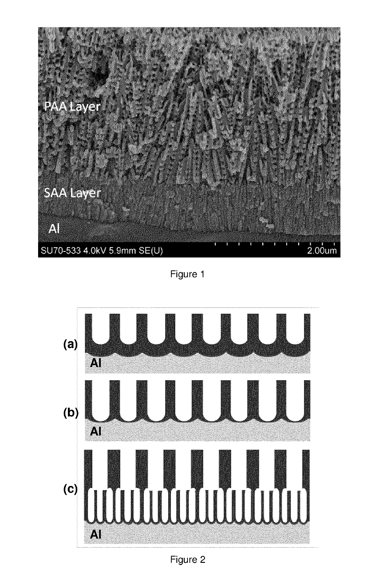
[0029]The method according to the present invention utilises a duplex anodising process which achieves the optimisation of the anodic layers and hence, the surface preparation of an anodisable metal, for example aluminium. The method of the present invention has the advantage that it overcomes the limitations between the respective forming voltages for the phosphoric acid anodising (PAA) and sulphuric acid anodising (SAA) treatments so that the parameters of each step may be chosen independently.
[0030]The first and second anodising steps can be carried out using any electrochemical process that forms an appropriate porous oxide layer on the metal. The formation of the oxide can be conducted simultaneously with an additional surface electrochemical process. For instance, the formation of the oxide can be accompanied simultaneously by an electrobrightening process. Electrobrightening of aluminium in acidic electrolytes is known to produce a porous oxide film similar to the anodising process. The parameters of the electrobrightneing process can be tailored to achieve reduction in surface roughness, to increase surface reflectance, while simultaneuously forming the anodic oxide required for the duplex anodic structure.
[0031]Another example of a simultaneous electrochemical process is the tailoring of the anodising procedure to form the porous oxide while simultaneously consuming the native oxide formed on the aluminium surface. Additionally, the parameters can be tailored to remove intermetallics from the aluminium matrix that oxidising at a slower rate than the aluminium metal. Such intermetallics can cause defect in the formed anodic layers which is problematic when optimum corrosion protection is required. In one embodiment of the present invention, the first anodic electrochemical treatment is used to prepare the aluminium surface and remove any intermetallics; and the second electrochemical process is then be conducted with the formed oxide thereby exhibiting optimum protection properties.
[0032]An advantage of the process according to the present invention is that it reduces the number of process steps therefore needed to prepare a metal surface. As the initial anodising treatment consumes the metal surfaces and any intermetallics, the surface is sufficiently prepared for the second treatment. The integrity and barrier properties achieved by the first anodising step are not particularly important, as the resulting first anodic layer is used as an adhesion and abrasion promoter; the integrity of the second anodic layer formed by the second anodising step being aided by the first anodic layer pre-treatment. This feature has the advantage of removing the requirement for up to six chemical treatments from a typical known anodising and electrobrightening cycle.
[0033]The multi-layer anodic coating according to the present invention suitably comprises a duplex anodic layer. The duplex anodic layer structure is formed by the double anodising process described herein which is conducted in two different electrolytes under conditions such that optimisation of the structure of the respective layers and of the overall duplex layer is achieved for optimised corrosion resistance together with optimised adhesion and abrasion properties as well as optimised for achieving full encapsulation of applied materials such as additional treatments that may be added to the exposed surface of the multi-layer anodic coating, such treatments possibly being formulated in the form of sol-gels.

Problems solved by technology

The thickness of the oxide layer is in the nanometer range which limits the performance of the metal against extreme mechanical and chemical attack.
If the pores are not sealed, the surface could have poor corrosion resistance.
Both natural and hydrothermally induced hydration results in pore blocking near the surface of the anodised layer.
The presence of copper, as well as the random orientation of the pores, leads to difficulties with hydration sealing.
However, due to the carcinogenic nature of these materials, the use of chromate based processes are currently restricted or being eliminated from anodising industries.
However, on the other hand, due to surface hydration and small pore size of the resulting oxide layer, the adhesion of top coats and lacquers has been found to be inferior to that achieved using chromic acid anodising.
However, this treatment imparts extremely poor corrosion resistance to the metal.
However, in the process disclosed, the voltage used for the first anodising step is limited due to the mixture of acids used.
The voltage used in the anodising step described in WO 2006 / 072804 is limited due to the mixture of sulphuric acid and phosphoric acid.
The process disclosed in WO 2006 / 072804 also suffers from the disadvantage that the duplex anodic layer formed is not optimised for adhesion as the pore size is relatively small.
However, optimum surface adhesion is not achieved as this can only be provided by sulphate free anodised layers formed under larger potentials.
Thus, again, the duplex anodic layer formed is not optimised.
Thus, despite the development of anodising treatments for copper rich aluminium alloys, the corrosion protection afforded by the anodic layers is limited and does not provide the desired corrosion resistance.
However, there are some inherent problems associated with the combination of sol-gel chemistry and current anodising processes.
Migration of sol-gel materials into the aluminium oxide pores can also be limited.

Method used


Image

  • Method for forming a multi-layer anodic coating
  • Method for forming a multi-layer anodic coating
  • Method for forming a multi-layer anodic coating

Examples


example 1

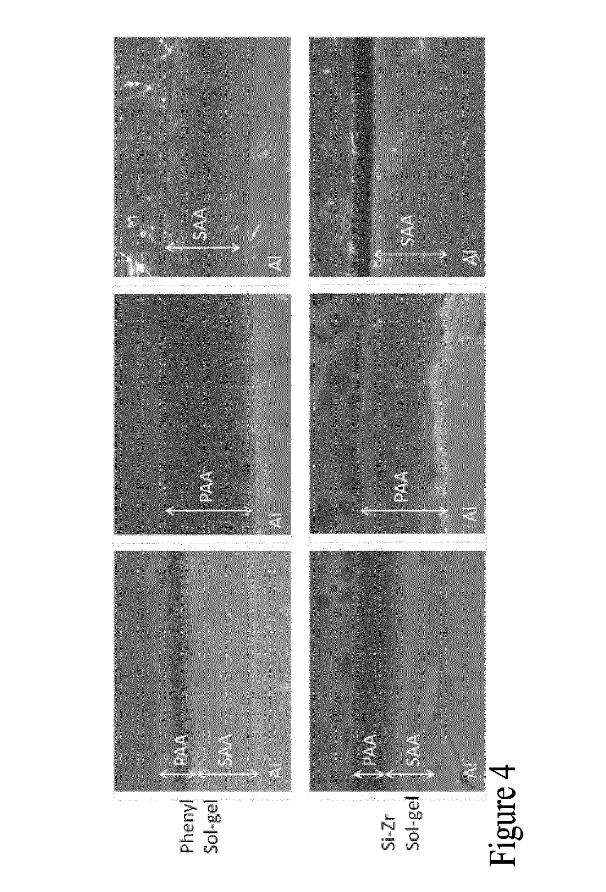
[0087]Two sol-gel coatings were synthesised and used as sealers for the anodic layers.

[0088]Phenyl Functionalised Sol-Gel

[0089]The silane precursor Phenyltriethoxysilane (PhTEOS 98%) (VWR International Ltd (Irl), 98%) was hydrolysed under acidic conditions by adding 5.2 ml of 0.04M HNO3 to 50.6 ml of silane precursor. 30.6 ml of absolute ethanol was immediately added to the mixture and left to stir for 45 minutes. 13.6 ml of de-ionised water was then added dropwise and the solution was left to stir for 24 h before use. The final molar ratio for the formulation was Silane:Ethanol:Water—1:2.5:3.5.

[0090]Silane-Zirconium Hybrid Sol-Gel

[0091]The silane precursor, 3-(trimethoxysilyl) propylmethacrylate (MAPTMS) (Sigma Aldrich, Irl, Assay (99%) was pre-hydrolysed using 0.01 N HNO3 for 45 min (A). Simultaneously, zirconium (IV) n-propoxide (TPOZ) (Sigma Aldrich, Ireland, Assay ˜70% in propanol) was chelated using Methacrylic acid (MAAH)(Sigma Aldrich), at a 1:1 molar ratio for 45 minutes (B...

example 2 (

Combined Electropolishing and Anodising)

[0122]Aluminium alloy 6063 is exposed to an aqueous electrolyte containing 40% H3PO4 at 70° C. The aluminium acts as an anode with a lead cathode. A current of approx 6 A / dm2 is applied. The applied potential is approximately 80V. This procedure results in a combined action of surface polishing as well as growth of a phosphate rich anodic layer on the surface of the metal. The process is conducted for 20 mins to achieve a high level of surface brightening. At the end of the combined polishing and anodising cycle the current is halved and the potential is allowed to float to achieve a lower steady state value. This current reduction process is repeated until a steady state voltage of 10V is achieved. The part is then removed from the phosphoric acid bath and rinsed in de-ionised water. The part is then exposed to a room temperature electrolyte of 25% H2SO4 and a current of 1.5 A / dm2 is applied for 20 mins. This grows a protective anodic layer b...

example 3 (

Surface Conditioning Process)

[0123]Aluminium alloy 2024 is exposed to an aqueous electrolyte containing 10% H3PO4 at 40° C. The aluminium acts as an anode with a lead cathode. A potential of 30V is applied. The process is conducted for 10 mins. This procedure results in a combined action of growing a phosphate rich anodic layer while also conditioning the metal prior to a second anodisation. The process aides in the removal of intermetallics in the alloy that do not anodise at the same rate as the aluminium matrix. At the end of the combined conditioning and anodising cycle the current is halved and the potential is allowed to float to achieve a lower steady state value. This current reduction process is repeated until a steady state voltage of 10V is achieved. The part is then removed from the H3PO4 bath and rinsed in de-ionised water. The part is then exposed to a room temperature electrolyte of 25% H2SO4 and a current of 1.5 A / dm2 is applied for 20 mins. This grows a protective a...


PUM

PropertyMeasurementUnit
voltageaaaaaaaaaa
diameteraaaaaaaaaa
diameteraaaaaaaaaa

Abstract

A method for producing a multi-layer anodic coating on a metal is described. The method comprises the steps of (i) placing the metal in a first electrolytic solution and applying a current to form a first anodic layer having a barrier region; (ii) reducing the applied current to cause a reduction in thickness of the barrier region; and (iii) placing the metal in a second electrolytic solution and applying a current to form a second anodic layer.

Description

REFERENCE TO RELATED APPLICATIONS[0001]The present application is a 371 National Stage Application of International Application No. PCT / EP2014 / 078700, filed Dec. 19, 2014, and claims priority to application no. GB 1322745.9, filed Dec. 20, 2013, the entire disclosures of which are incorporated herein by reference.FIELD[0002]The present invention relates to a method for forming a multi-layer anodic coating, in particular, a duplex anodic layer, on an anodisable metal.BACKGROUND[0003]Aluminium is used extensively for lightweight structures such as automotive and aerospace components where a combination of strength and corrosion resistance is essential. Aluminium owes its inherent corrosion resistance to a naturally occurring passive oxide which forms on the metal when exposed to the atmosphere. The thickness of the oxide layer is in the nanometer range which limits the performance of the metal against extreme mechanical and chemical attack. Electrochemical processes have been investig...

Claims


Application Information

Patent Timeline
Patent Type & Authority Patents(United States)
IPC IPC(8): C25D5/00C25D11/12C25D11/00C25D11/02C25D11/24C25D11/16C25D11/08C25D11/04C25D11/06
CPCC25D11/12C25D11/024C25D11/04C25D11/246C25D11/08C25D11/16C25D11/24C25D11/06
Inventor DUFFY, BRENDANWHELAN, MICHAEL
Owner TECHCAL UNIV DUBLIN
Learn More