Device and method for administering particle beam therapy

a technology of particle beam therapy and device, applied in the field of device and method for administering particle beam therapy, can solve the problem of huge cost and deep excavation of the arrangemen

Active Publication Date: 2011-11-08
MOORE FAMILY PROPERTIES LLC
View PDF33 Cites 49 Cited by
  • Summary
  • Abstract
  • Description
  • Claims
  • Application Information

AI Technical Summary

Problems solved by technology

Because of the size of the particle beam generator, the magnets required to deflect the beam by a total of close to 180 degrees, and the gantry, this arrangement requires deep excavation at huge cost.

Method used


Image

  • Device and method for administering particle beam therapy
  • Device and method for administering particle beam therapy
  • Device and method for administering particle beam therapy

Examples


Embodiment Construction

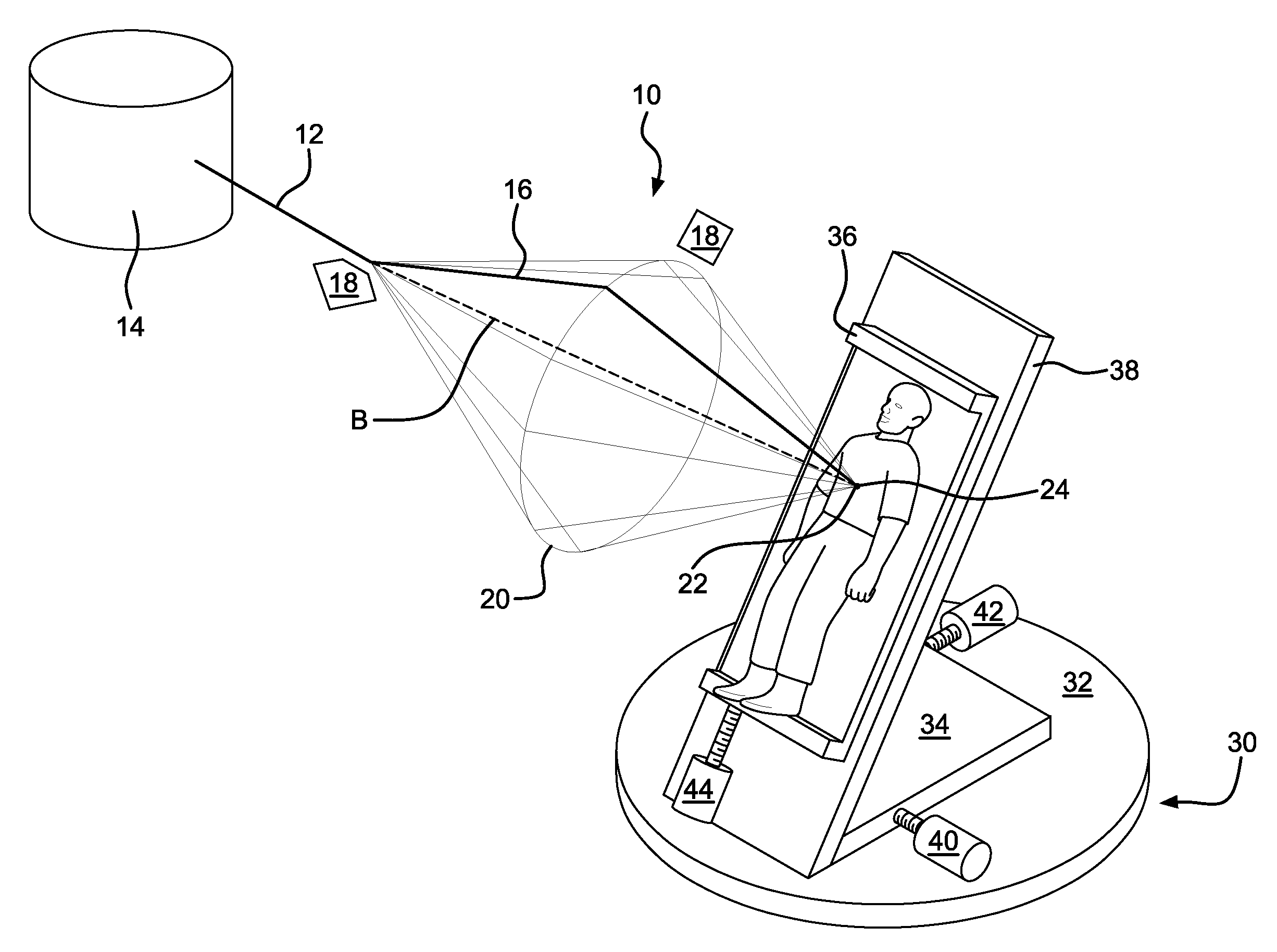
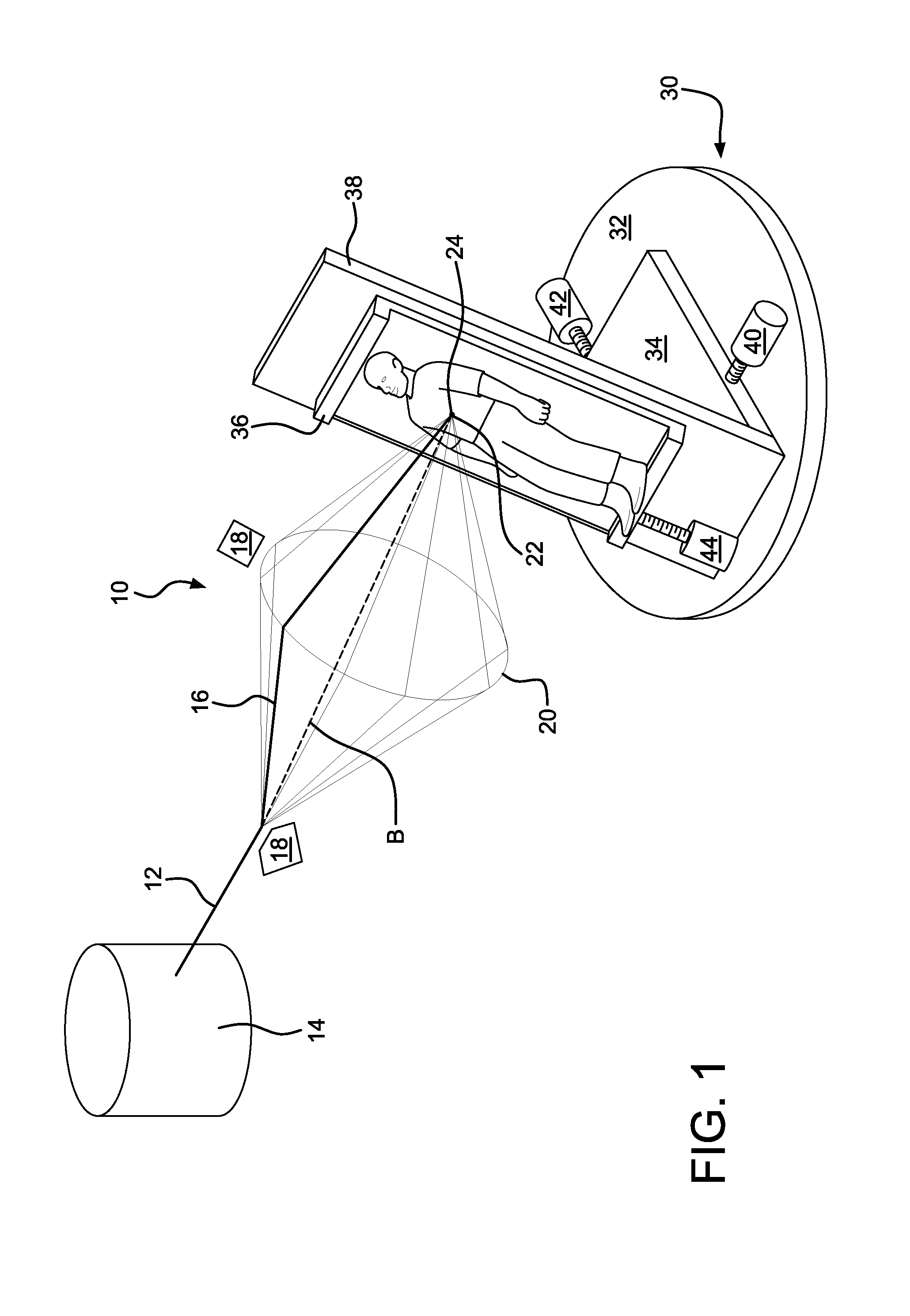
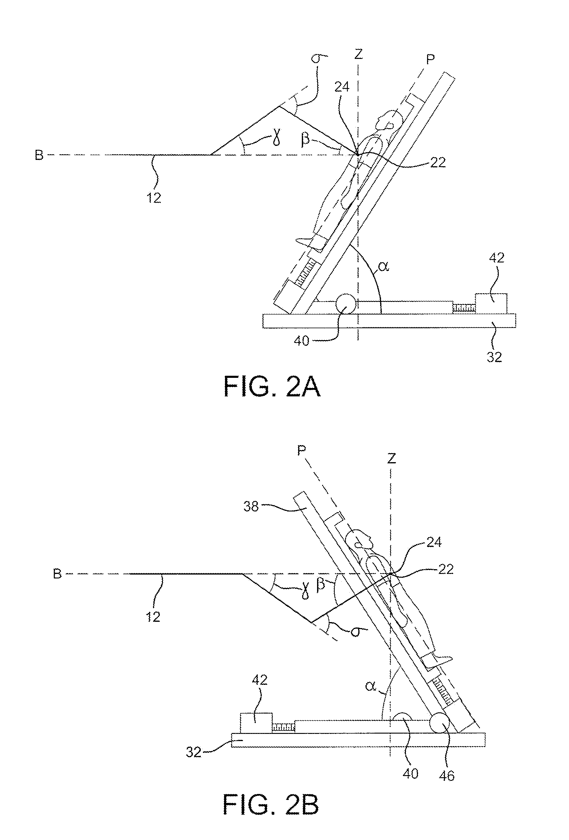
[0015]FIG. 1 shows a representation of an embodiment of the system 10 of the present invention. A beam 12 is generated by a beam generator 14, which may be a cyclotron or similar device. While the beam may be any type of beam, including optical and particle beams, “beam” or “particle beam” as used herein is intended to describe any suitable type of beam. The beam is directed along a path 16 by path guides 18, which are preferably magnets for a particle beam, but which may be any device suitable for deflecting the path of a given type of beam. As shown in FIGS. 2A-2D, the path 16 is bent at a first angle γ and a second angle σ. While the first angle γ and the second angle σ remain constant for a particular treatment cycle, the beam path varies in a rotation around axis B, which is coaxial with the path of the beam 12 prior to deflection at the first angle γ, as shown in FIGS. 1 and 4A. The angles γ and σ can be any angles that provide the desired system geometry. The rotation of the ...


PUM


Abstract

A device for circumscribing a target site with a beam. The target site is located within a target body. The path of the beam is varied rotationally so as to form a cone with an isocenter at the cone's apex. The isocenter is fixed on the approximate center of the target site. The target body is rotated about a vertical axis passing approximately through the center of the target site, and the rates of rotation of the beam path and body, respectively correspond so that the beam intersects an axis passing through the target site at an approximately constant angle.

Description

BACKGROUND OF THE INVENTION[0001]It is known to use directed beams of particles, including but not limited to protons, heavier ions (such as carbon), and mesons, to attack and destroy cancer cells. Particle therapy has an advantage over traditional radiation therapy in that the particle beam can be directed to a particular depth within a patient's body; because, unlike an x-ray beam, the particle beam deposits little energy in the tissue through which it passes, but deposits a large amount of energy at its end point, the beam can kill cancer cells with minimal damage to intervening tissue. Dose to the tissue surrounding the tumor is further reduced by arranging for the beam to reach the tumor from many different directions, such as over an arc of up to 360 degrees. Conventional particle therapy involves generating a beam of fast-moving particles in a particle accelerator or a cyclotron. The beam is then directed along a desired path toward a patient. Because the beam must be deliver...

Claims


Application Information

Patent Timeline
Patent Type & Authority Patents(United States)
IPC IPC(8): A61N5/10G21K5/10
CPCA61N5/10A61N5/1081G21K1/093G21K5/04A61N2005/0641A61N2005/1087A61N5/1077
Inventor MOORE, JOHN F.
Owner MOORE FAMILY PROPERTIES LLC
Why Eureka
Try Eureka