
Chemical injection system and chemical delivery process/method of injecting into an operating power reactor

a technology of chemical injection system and power reactor, which is applied in the direction of nuclear engineering, nuclear elements, greenhouse gas reduction, etc., can solve the problem of raising the pressure required for chemical solutions

Inactive Publication Date:
View PDF6 Cites 2 Cited by
  • Summary
  • Abstract
  • Description
  • Claims
  • Application Information

AI Technical Summary

Benefits of technology

The injection system described in this patent is designed to deliver a chemical solution to a power reactor in a concentrated form, which is then diluted by the system before being discharged. This method has several benefits, including minimizing chemical loss, allowing for higher concentrated solutions, eliminating the need for chemical dilution, raising the chemical solution to the required pressure, preventing solid precipitation, and depositing fresh chemical on new crack surfaces during power reactor operation.

Problems solved by technology

Fourth, it raises the chemical solution to the pressure required for injection.

Method used


Image

  • Chemical injection system and chemical delivery process/method of injecting into an operating power reactor
  • Chemical injection system and chemical delivery process/method of injecting into an operating power reactor
  • Chemical injection system and chemical delivery process/method of injecting into an operating power reactor

Examples


Embodiment Construction

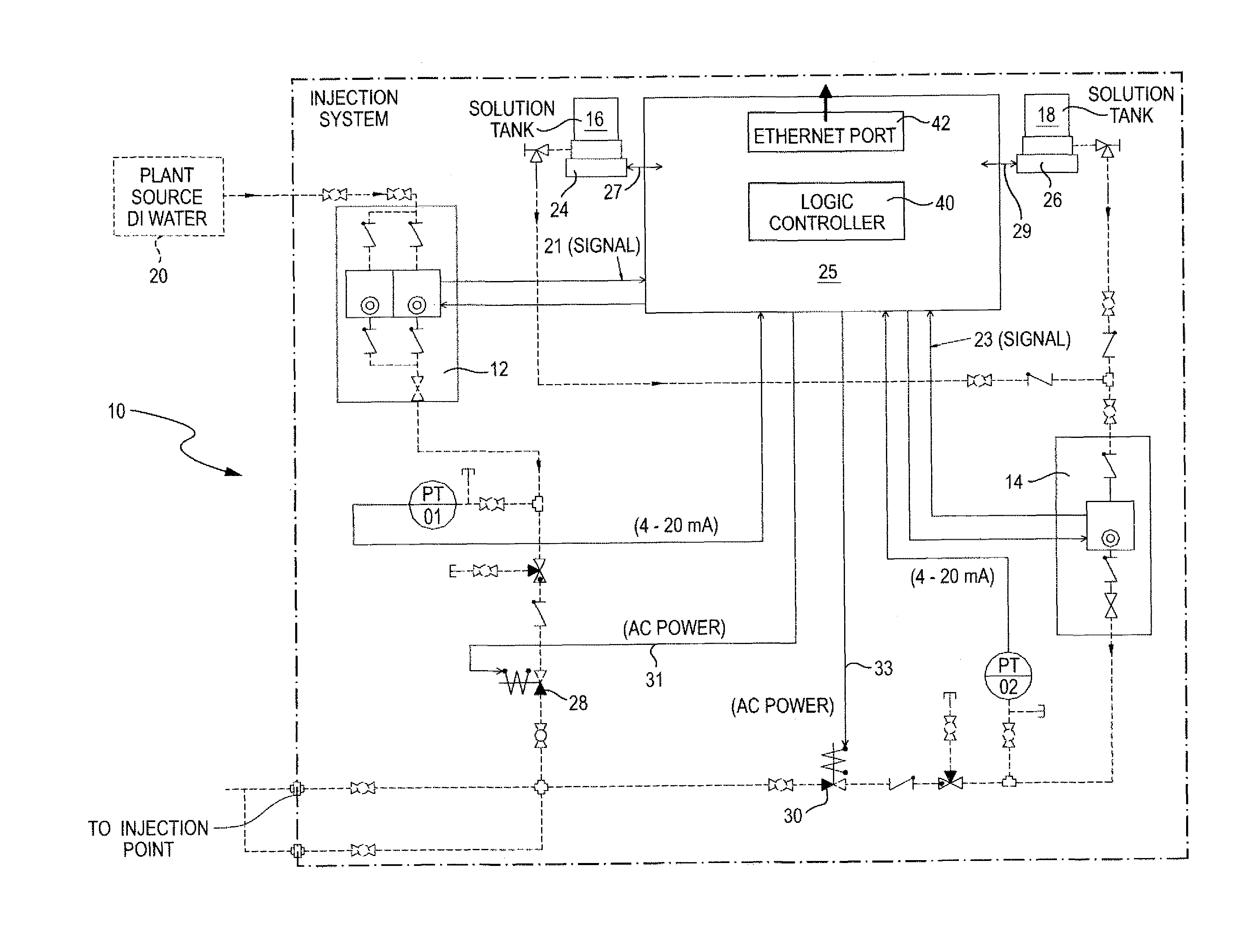
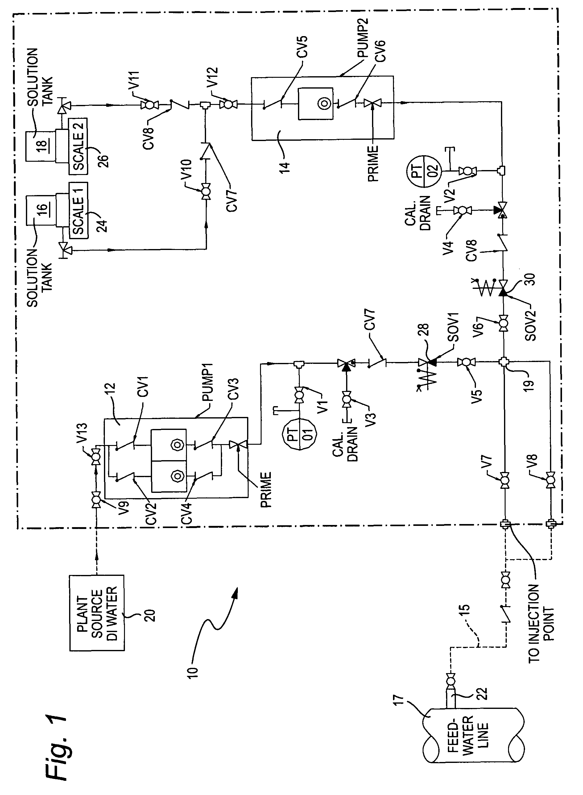
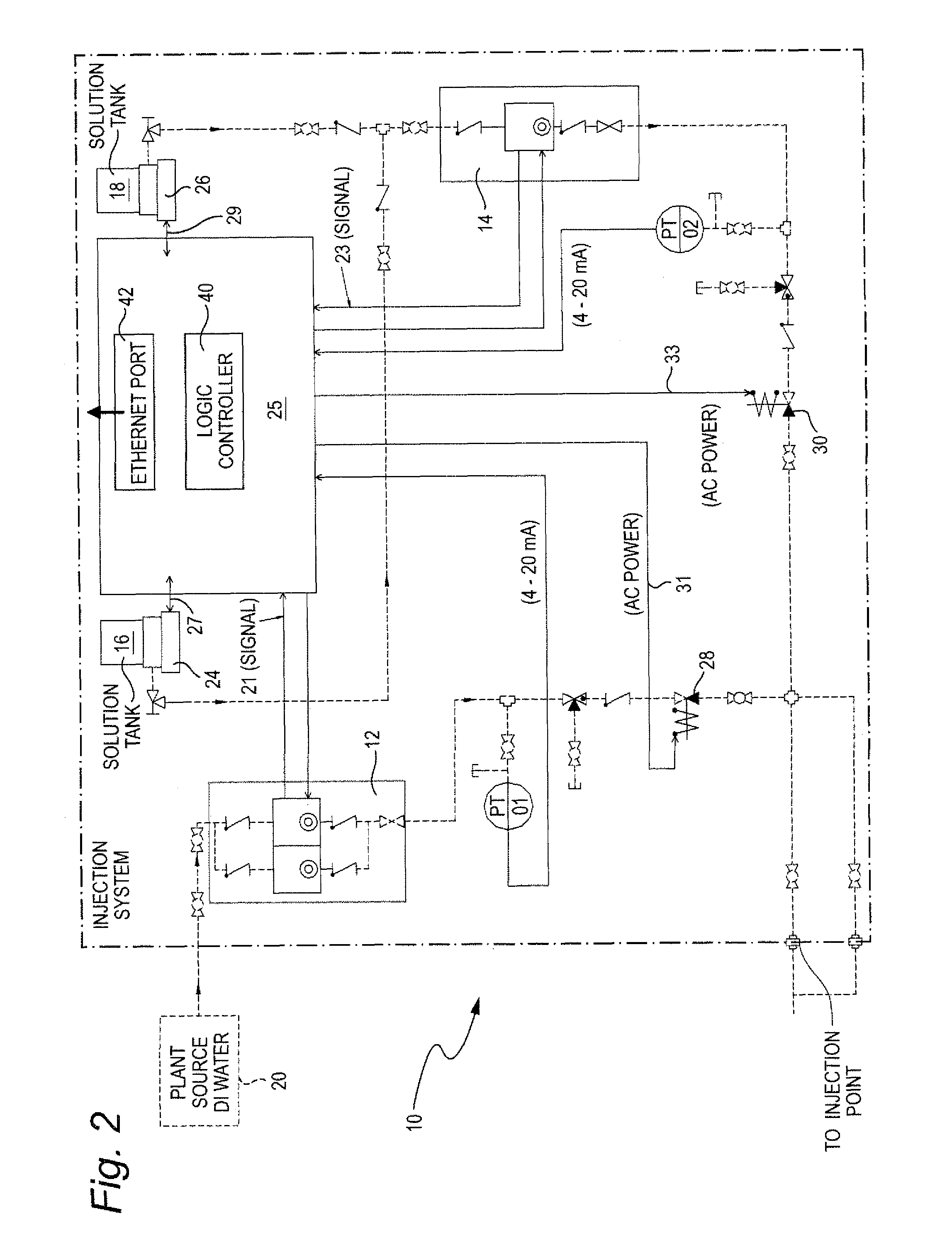
[0013]FIG. 1 is a schematic flow diagram of an on-line injection system 10 used to inject a chemical solution into an operating reactor (not shown) to mitigate intergranular stress corrosion cracking. The system 10 includes two injection pumps, 12 and 14, operating in unison. One pump 14 pumps a concentrated chemical solution from alternative ones of two makeup tanks 16 or 18, while the other pump 12 assists in shortening the chemical solution delivery time by diluting the solution with DI water from a plant source 20. The discharges of both pumps 12 and 14 are combined and mixed at line junction 19 prior to exiting the skid and being injected into the reactor, i.e., via the feedwater line 17. This dilution of the chemical solution accomplishes the task of reducing the residence time of the chemical within the transit tubing 15, while facilitating the dilution of the solution.

[0014]The system 10 injects the chemical solution into either a primary or auxiliary system through tap 22. ...


PUM


Abstract

An injection system designed to deliver a chemical solution into a reactor through feedwater system taps during normal operating condition of a power reactor is disclosed. The process of delivery is via positive displacement pumps. Injection of chemical is in a concentrated solution form, which is internally diluted by the system prior to discharging from the skid. The injection system minimizes chemical loss due to deposition on the transit line, enables a higher concentrated solution to be used as the injectant, eliminates the time consuming laborious process of chemical dilution, raises chemical solution to the pressure required for injection, prevents solid precipitations out of solution at the injection pump head through the use of a flush solution, and deposits fresh chemical on new crack surfaces that develop during a power reactor start-up, shutdown and operation.

Description

[0001]The present invention relates to nuclear power reactors, and more particularly to an on-line injection system that provides the ability to inject a chemical solution into nuclear power reactors after startup to treat the reactor internals to thereby mitigate intergranular stress corrosion cracking (IGSCC).BACKGROUND OF THE INVENTION[0002]It is known to use noble metal chemicals in conjunction with hydrogen gas injection to mitigate intergranular stress corrosion cracking (IGSCC) in nuclear power reactors. As a catalyst, noble metal solution is injected into a reactor to assist in the recombination of oxygen and hydrogen. Delivery of noble metals for power reactors is typically done during hot standby, mode 3. No power is generated during this mode when the noble metal is being injected, resulting in a substantial loss of expensive critical path time.[0003]In addition, during the startup period of a power reactor, hydrogen cannot be injected with the current system configuratio...

Claims


Application Information

Patent Timeline
Patent Type & Authority Patents(United States)
IPC IPC(8): G21C9/00
CPCG21C19/28G21C17/0225Y02E30/30
Inventor TRAN, LUONG CAMDIAZ, THOMAS P.HETTIARACHCHI, SAMSONSHU, PAUL Y.SIEGWARTH, DAVID P.
Learn More