Global calibration for stereo vision probe

a global calibration and vision probe technology, applied in the field of precision measurement instruments, can solve the problems of prohibitive cost and/or complexity of such systems for many applications, and achieve the effects of low cost, prohibitive cost and/or complexity of such systems, and simple and efficient calibration

Active Publication Date: 2011-11-08
MITUTOYO CORP
View PDF13 Cites 51 Cited by
  • Summary
  • Abstract
  • Description
  • Claims
  • Application Information

AI Technical Summary

Benefits of technology

[0012]The global calibration method is particularly advantageous for a practical and low cost portable and / or “desktop” version of a multi-camera vision-based touch probe locating system, although its use is not restricted to such systems. It should be appreciated that the features of prior art systems, such as separate calibration procedures for various types of errors and / or the use of fixed marker arrangements in addition to the markers included on the probe body, may make the cost and / or complexity of such systems prohibitive for many applications. It should be appreciated that for “desktop” systems, ease-of-use is a critical factor, in that such systems may be intended for use by relatively unskilled or occasional users that demand the best possible calibration results while using the simplest possible calibration objects and the simplest and most comprehensible set of operations. It should also be appreciated that “desktop” systems may be constructed using low cost materials and techniques, such that interchangeable parts such as probe styli or tips are formed imprecisely and / or cameras and / or mechanical frames may be relatively more susceptible to thermal or physical distortions, or the like. Thus, for desktop systems, simple and efficient calibration may assume relatively more importance than it has in prior art systems, such as industrial and medical systems.

Problems solved by technology

It should be appreciated that the features of prior art systems, such as separate calibration procedures for various types of errors and / or the use of fixed marker arrangements in addition to the markers included on the probe body, may make the cost and / or complexity of such systems prohibitive for many applications.

Method used


Image

  • Global calibration for stereo vision probe
  • Global calibration for stereo vision probe
  • Global calibration for stereo vision probe

Examples


Embodiment Construction

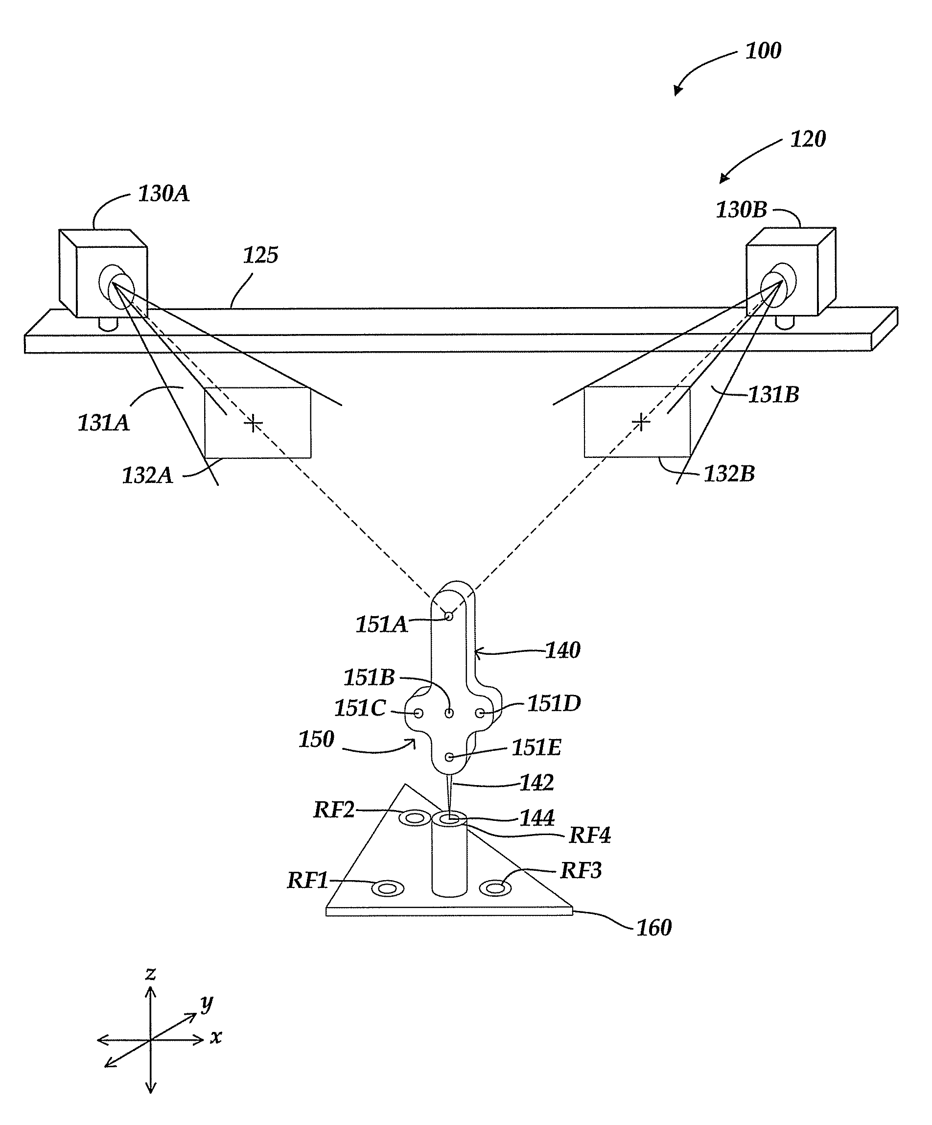
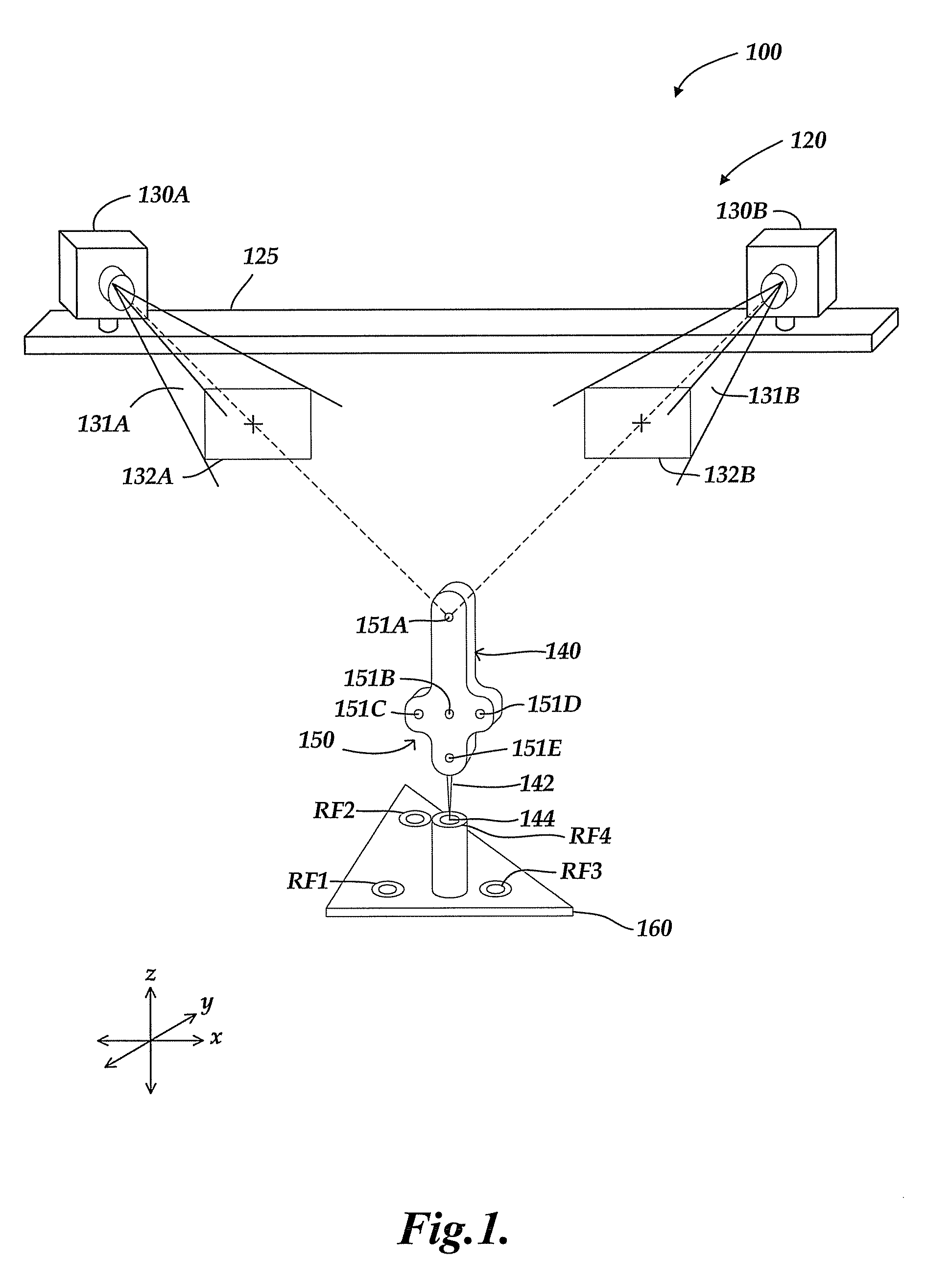
[0023]FIG. 1 is a diagram of a first exemplary embodiment of a multi-view touch probe system calibration arrangement 100. The present arrangement may be interchangeably referred to as a stereo-vision touch probe system calibration arrangement 100, since this particular embodiment uses a typical dual-camera stereo vision arrangement. The calibration arrangement 100 includes a stereo vision touch probe system 120 and a portable calibration jig 160. The stereo vision touch probe system 120 includes a mounting frame 125, two cameras 130A and 130B, and a touch probe 140. The body of the touch probe 140 includes a marker pattern 150, which includes a set of individual markers 151A-151E that are imaged by the stereo vision cameras 130A and 130B. Each of the individual markers 151A-151E may comprise IR LEDs or other light sources or any other types of markers which may be reliably imaged by the stereo vision cameras. The end of the touch probe 140 also includes a stylus 142 with a probe tip...


PUM


Abstract

A method for global calibration of a multi-view vision-based touch probe measurement system is provided which encompasses calibrating camera frame distortion errors as well as probe form errors. The only required features in the calibration images are the markers on the touch probe. The camera frame distortion calibration comprises a process that depends on a portable calibration jig and the touch probe, but that process is unaffected by probe form distortion errors in the touch probe and / or tip. The probe tip position calibration depends on applying the results of the camera, frame distortion calibration. When the same probe tip is used throughout the global calibration, the probe tip position calibration uses images from the set of images used by the camera frame distortion calibration. The global calibration method is particularly advantageous for low cost portable versions of multi-view vision-based touch probe measurement systems.

Description

CROSS-REFERENCE(S) TO RELATED APPLICATION(S)[0001]This application is a continuation-in-part of U.S. patent application Ser. No. 11 / 694,837, filed Mar. 30, 2007, priority from the filing date of which is hereby claimed under 35 U.S.C. §120.FIELD OF THE INVENTION[0002]The invention relates generally to precision measurement instruments, and more particularly to a system and method of global calibration for a multi-view vision-based touch probe locating system that is used in a coordinate measuring system.BACKGROUND OF THE INVENTION[0003]Various types of touch probe coordinate measuring systems are known. In the type of touch probe coordinate measuring system under consideration here, the workpiece is measured by using a multi-camera vision system to determine the location of the touch probe when the touch probe tip is at a desired location on a workpiece surface. A visual marker pattern is located on the body of the touch probe, with the markers being imaged by at least two cameras o...

Claims


Application Information

Patent Timeline
Patent Type & Authority Patents(United States)
IPC IPC(8): G01D18/00
CPCG01B21/042G01S5/16G01S11/12G01B5/008G01B11/002
Inventor BRYLL, ROBERT KAMIL
Owner MITUTOYO CORP
Why Eureka
Try Eureka