Power tool

a power tool and power technology, applied in the field of power tools, can solve the problems of de-energized motor and unlatching control buttons no hand is free to steady the plunge saw or a work piece,

Active Publication Date: 2011-11-15
BLACK & DECKER INC
View PDF10 Cites 7 Cited by
  • Summary
  • Abstract
  • Description
  • Claims
  • Application Information

AI Technical Summary

Benefits of technology

[0012]Typically, the channel is in part of a body fixed in relation to the foot plate while the control button is mounted to the housing. This has the advantage that the same hand that operates the control button to select plunge or blade change modes can also grasp the handle and push the housing towards the foot plate. However, the location of the control button and the groove can be reversed.
[0030]Preferably, the interlock comprises a spindle lock for locking the blade against rotation, wherein the spindle lock is operable by the control shaft after operation of the housing lock. The spindle lock is only used when the blade change position has been adopted and a blade change operation is desired. The spindle lock immobilizes the blade against rotation to enable efficient detachment. The spindle lock is inoperable prior to operation of the housing lock thereby ensuring that energization of the motor is prevented and that the blade and housing are locked in situ. When a blade change operation is complete, the housing and spindle locks can be released and the housing and the blade can return, through upward bias of a plunge spring, to the parked position.

Problems solved by technology

However, if ever the housing is accidentally released it naturally returns to the parked position under the bias of a plunge spring.
No hand is free to steady the plunge saw.
However, if ever the switch button is accidentally released it naturally de-energizes the motor and unlatches the control button.
No hand is free to steady the plunge saw or a work piece upon which the plunge saw is performing a cutting operation.

Method used


Image

  • Power tool
  • Power tool
  • Power tool

Examples


Embodiment Construction

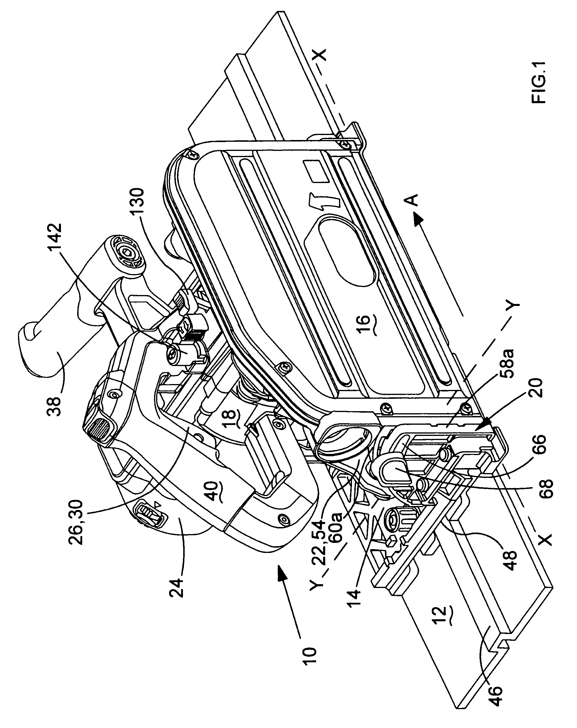
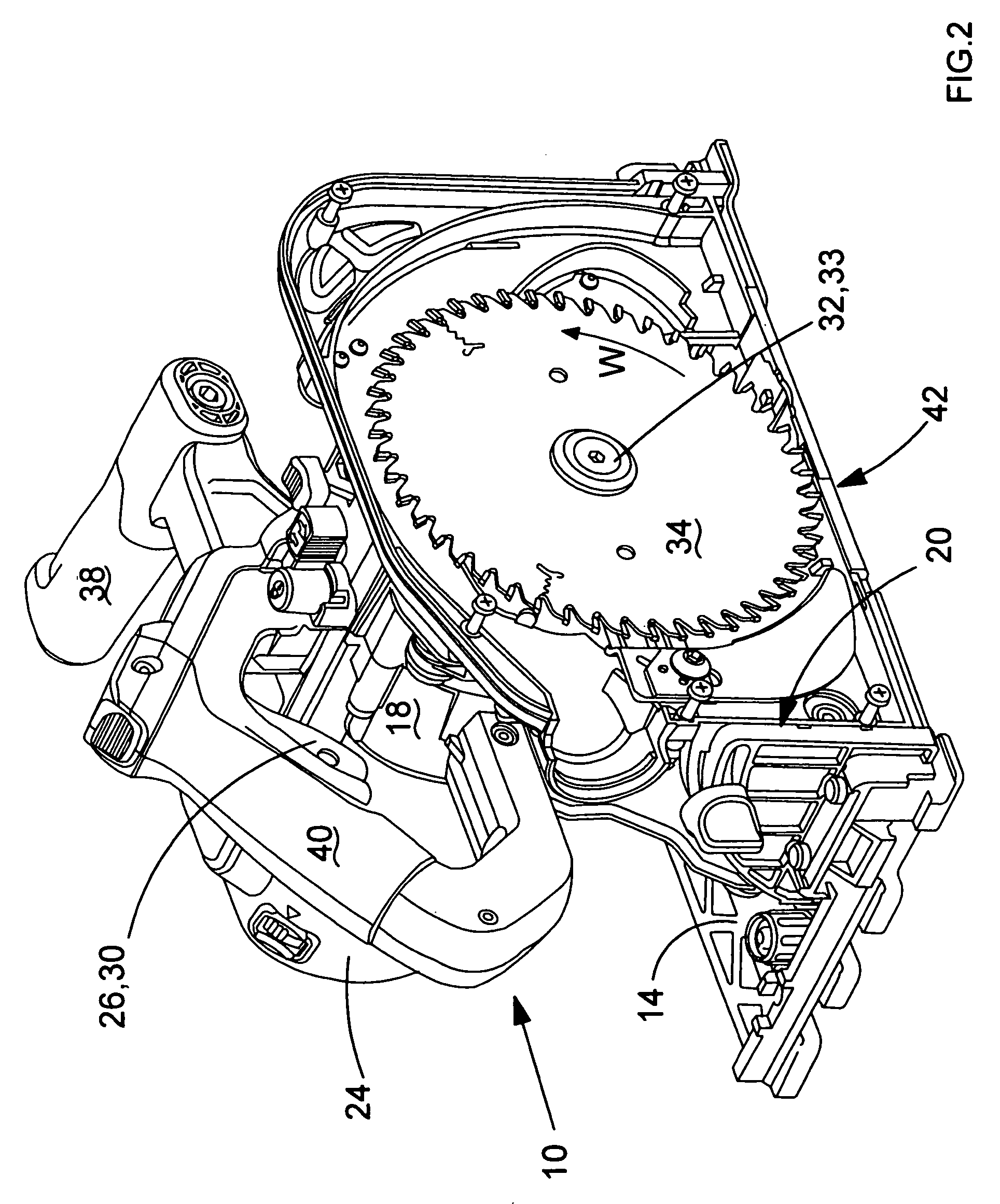
[0054]Referring to FIG. 1 to 4, a hand-held tool in the form of a plunge-cut circular saw 10 is designed to slide along a guide 12. The saw comprises a foot plate 14, a blade guard 16 and a housing 18. The housing is pivotally mounted to the guard at a bevel hinge 20. The guard is pivotally mounted to the foot plate at a plunge pivot 22. The housing has an electric motor 24 connected, via and on-off switch 26, to a power source (not shown). The manually operable on-off switch has a switch button 30. The motor's driving rotation is transmitted via a motor spindle 31, a gear box, a main spindle, and a coupling 32. These transmission components are collectively called a spindle arrangement 33. The motor is coupled to the spindle arrangement via the motor spindle. A circular saw blade 34 is coupled to the spindle arrangement via the coupling.

[0055]Referring to FIGS. 5A and 5B, the bevel hinge 20 is so-called because it enables bevel cutting by the blade. This is when the housing 18, bla...


PUM

PropertyMeasurementUnit
bevel angleaaaaaaaaaa
lengthaaaaaaaaaa
displacementaaaaaaaaaa

Abstract

A power tool comprising a housing displaceably mounted to a foot plate, a blade, a motor, an electric switch and an interlock for controlling movement of the housing with respect to the foot plate. The interlock has a control button mounted to one of the housing or foot plate which cooperates with a channel fixed in relation to the other of the housing or foot plate. The control button can select between a plunge cut mode wherein the blade can protrude below the foot plate, or a blade change mode wherein the blade is prepared for a blade change operation. The channel comprises a major leg in communication with a minor leg. Cooperation between the button and the major leg selects the plunge cut mode. Cooperation between the button and the minor leg selects the blade change mode. The interlock may also comprise a housing lock and a spindle lock.

Description

FIELD OF THE INVENTION[0001]The invention relates to a power tool with a motor housing movably mounted on a foot plate. The power tool is normally biased by a plunge spring into a “parked” position where the housing is retracted away from the foot plate. The power tool's electric motor is connected to a power source via an on-off switch activated by a switch button.BACKGROUND OF THE INVENTION[0002]If the power tool is a plunge-cut circular saw its circular saw blade is shielded by a guard, except for when the housing is pushed towards the foot plate so that the saw blade protrudes through an aperture in the foot plate to perform a cutting operation. The housing and saw blade of a plunge-cut circular saw move relative to the foot plate about a pivot connecting the housing and foot plate.[0003]If the power tool is a router it normally does not have a guard because its router bit is at least partially shielded by a pair of support columns, but the router blade does protrude through an ...

Claims


Application Information

Patent Timeline
Patent Type & Authority Patents(United States)
IPC IPC(8): B23D47/02
CPCB27B9/02B27G19/04Y10T409/306608Y10T83/7872
Inventor SARGEANT, PAULKEENLYSIDE, SCOTTTHOMAS, ROGERHERTING, RAINER
Owner BLACK & DECKER INC
Why Eureka
Try Eureka