Moisture removal system

a technology of moisture removal system and moisture removal, which is applied in the field of moisture removal system, can solve the problems of complex installation and/or high cost of systems disclosed in the prior art, particularly in the direction of domestic heating details, secondary air addition to fuel, etc., and achieves the effect of simple and low cost construction and readily installed

Active Publication Date: 2011-11-15
FERNANDES JOAO PASCOA
View PDF92 Cites 20 Cited by
  • Summary
  • Abstract
  • Description
  • Claims
  • Application Information

AI Technical Summary

Benefits of technology

By locating the inlet opening and the outlet opening together at one end of the substrate layer, air handling equipment can be efficiently setup in communication with the substrate layer. Furthermore the resulting passage which extends alongside the channels is more continuous with the inlet plenum so as to result in a more even pressure and flow distribution for optimum moisture collection when air is circulated through the channels.
When providing only suction on the channels to maintain the supporting surface at a vacuum pressure, a simple and low cost construction results which can be readily installed as a substrate layer between finishing materials and existing walls.

Problems solved by technology

Moisture is particularly a problem in foundation areas of concrete structures in which the moisture can penetrate through concrete walls and floors into occupied spaces of the building.
In each instance in the prior art, the systems are not well suited for installation as a substrate ready to accept finishing materials thereon and in a manner in which airflow for collecting moisture is optimized through a substrate area.
In other instances the systems disclosed in the prior art are complex to install and / or costly.
The system works well, however in some instances the airflow pattern may be limited to particular wall configurations and the many redirections of air through manifold or plenum sections of the system do not always ensure even pressure and flow distribution for optimum moisture collection.

Method used


Image

  • Moisture removal system
  • Moisture removal system
  • Moisture removal system

Examples


Embodiment Construction

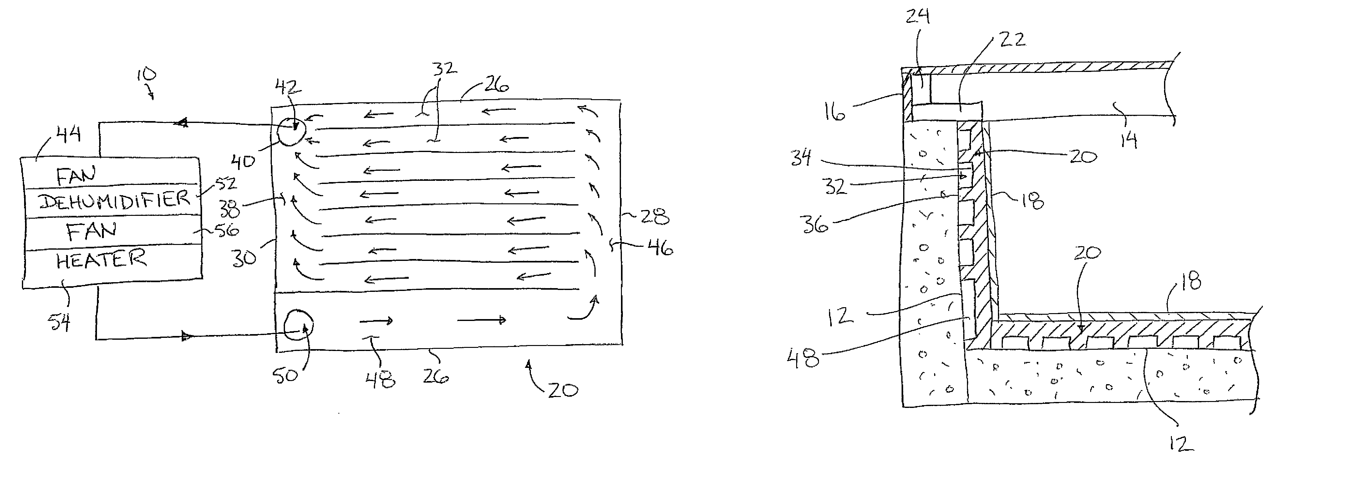
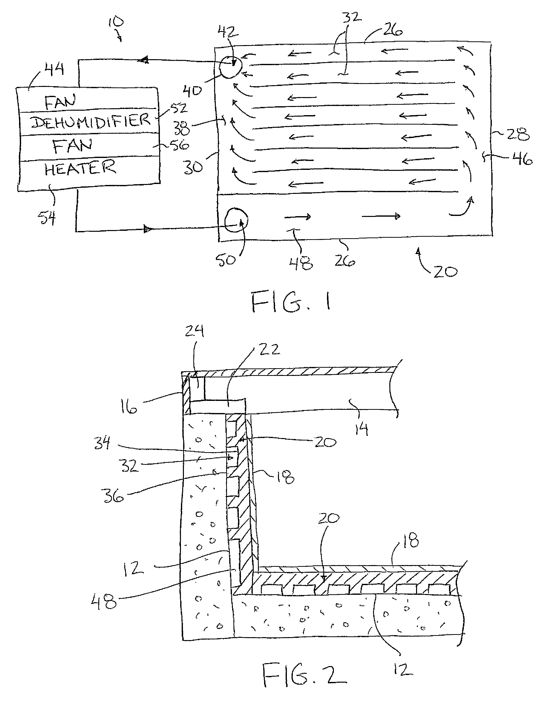
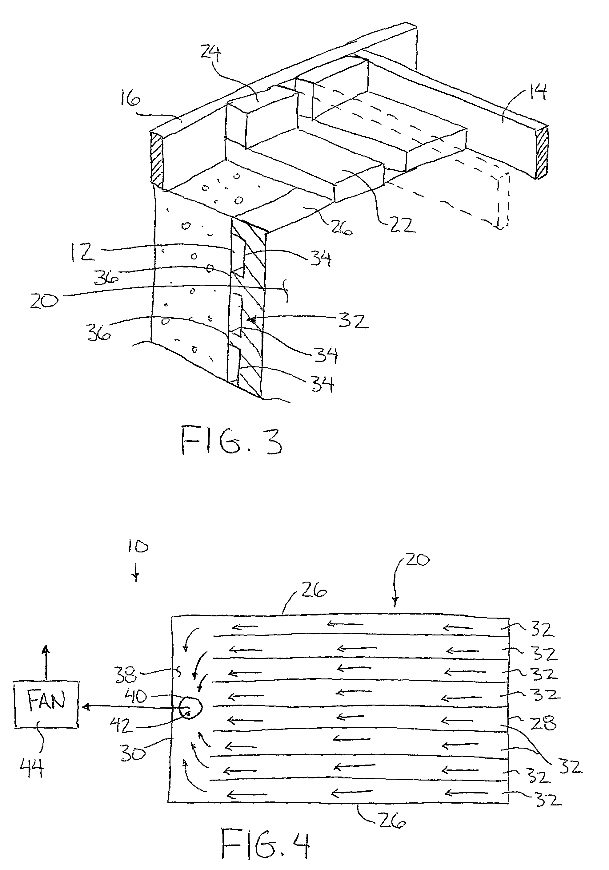
Referring to the accompanying figures there are illustrated moisture removal systems generally indicated by reference numeral 10. The systems 10 are particularly suited for removing moisture from a supporting surface 12, for example a floor or a wall. Although variations to the systems 10 are described and illustrated herein, the common features will first be described.

The moisture removal system 10 is particularly suited for mounting as a substrate layer against a concrete wall or floor, for example a foundation wall in a building basement. When used as a substrate layer lining the inside of a concrete foundation wall, a plurality of floor joists are typically supported parallel and spaced apart from one another on top of the wall to span generally horizontally between two spaced apart walls. The joists 14 are typically joined by a header 16 resting on the top side of the wall.

The substrate layer of the system is formed of a plurality of panels of polystyrene or other suitable self...


PUM

PropertyMeasurementUnit
vacuum pressureaaaaaaaaaa
areaaaaaaaaaaa
pressureaaaaaaaaaa

Abstract

A sheathing layer spans a supporting surface from which moisture is to be removed. In one exemplary system, ventilation channels extend between opposed ends of the substrate layer, communicating with an outlet opening at one end and with a duct at the opposing end which in turn communicates with an inlet opening at the same end of the substrate layer as the outlet opening. A fan is arranged to circulate air through channels from the inlet opening to the outlet opening to replace humid air in the channels with drier replacement air. In another example, a substrate layer includes ventilation channels communicating only between the supporting surface and an outlet opening. The outlet opening connects to a fan which maintains the channels at a vacuum pressure to withdraw moisture therefrom.

Description

This application claims foreign priority benefits from Canadian Patent Application 2,594,220, filed Jun. 15, 2007.FIELD OF THE INVENTIONThe present invention relates to moisture removal systems arranged for removing moist air from a supporting surface, and more particularly comprises a moisture removal system for a supporting surface of the type for receiving finishing material thereon in which the system comprises a substrate layer for removing moist air between the supporting surface and the finishing material.BACKGROUNDIt is known to be desirable to remove excess moisture in buildings to prevent the accumulation of mold and for the comfort of occupants of the building. Moisture is particularly a problem in foundation areas of concrete structures in which the moisture can penetrate through concrete walls and floors into occupied spaces of the building.The following US patents disclose several examples of systems related to moisture removal in a building: U.S. Pat. No. 5,893,216 be...

Claims


Application Information

Patent Timeline
Patent Type & Authority Patents(United States)
IPC IPC(8): F26B11/02
CPCE04B1/7069F24F3/153F26B21/00F26B21/08
Inventor FERNANDES, JOAO PASCOA
Owner FERNANDES JOAO PASCOA
Why Eureka
Try Eureka