

Chain connecting link
a technology of connecting links and chains, applied in the direction of chain elements, driving chains, chain fastenings, etc., can solve the problems of increasing production expenditure, affecting the disassembly and disassembly of chain connecting links in the kenter configuration, and affecting the disassembly of chain connecting links. , to achieve the effect of facilitating the disassembly and disassembly of chain connecting links
- Summary
- Abstract
- Description
- Claims
- Application Information
AI Technical Summary
Benefits of technology
Problems solved by technology
Method used
Image

Examples
Embodiment Construction
.
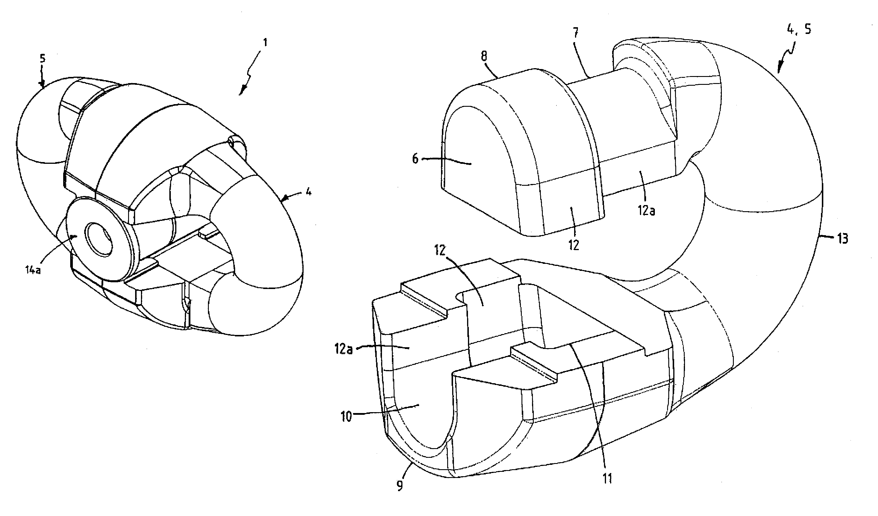
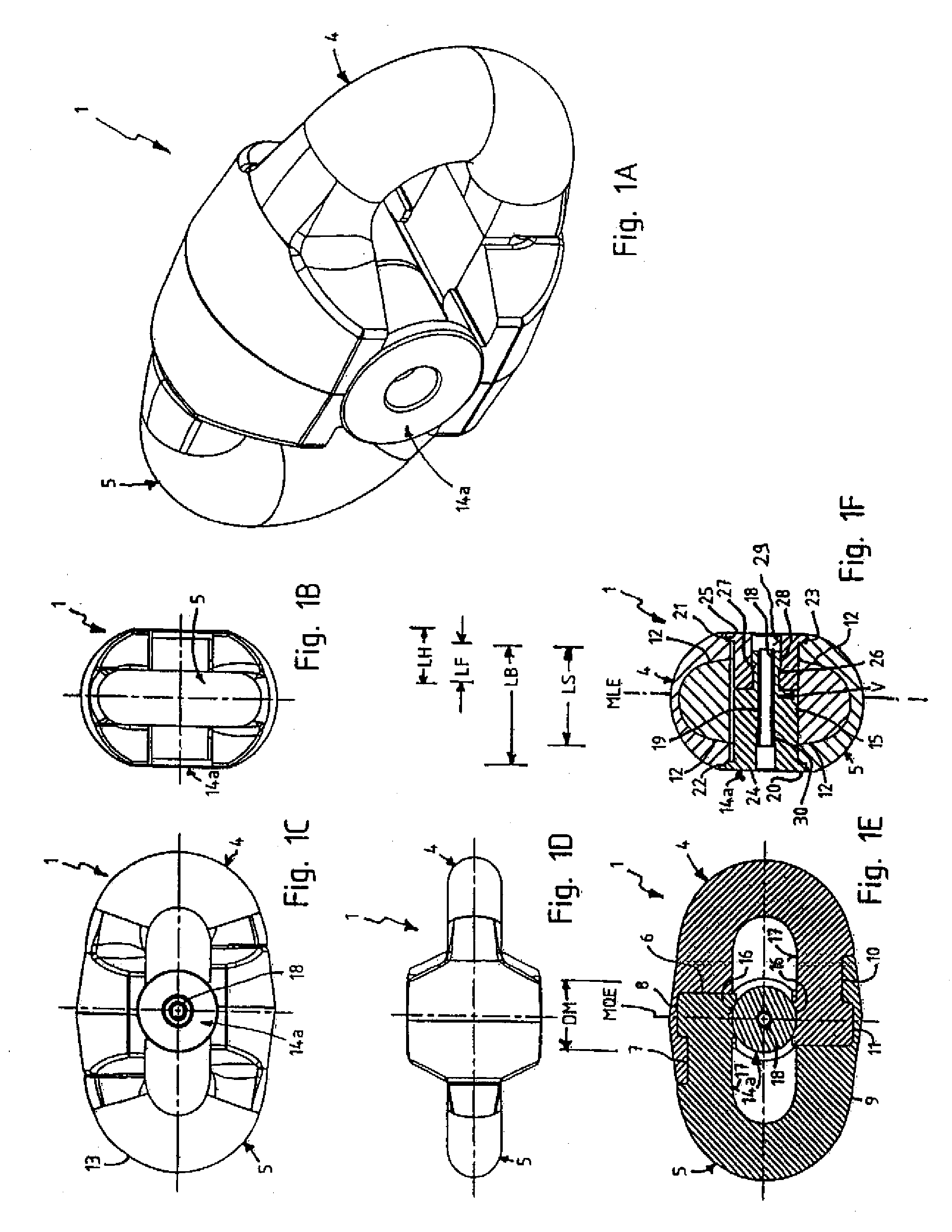
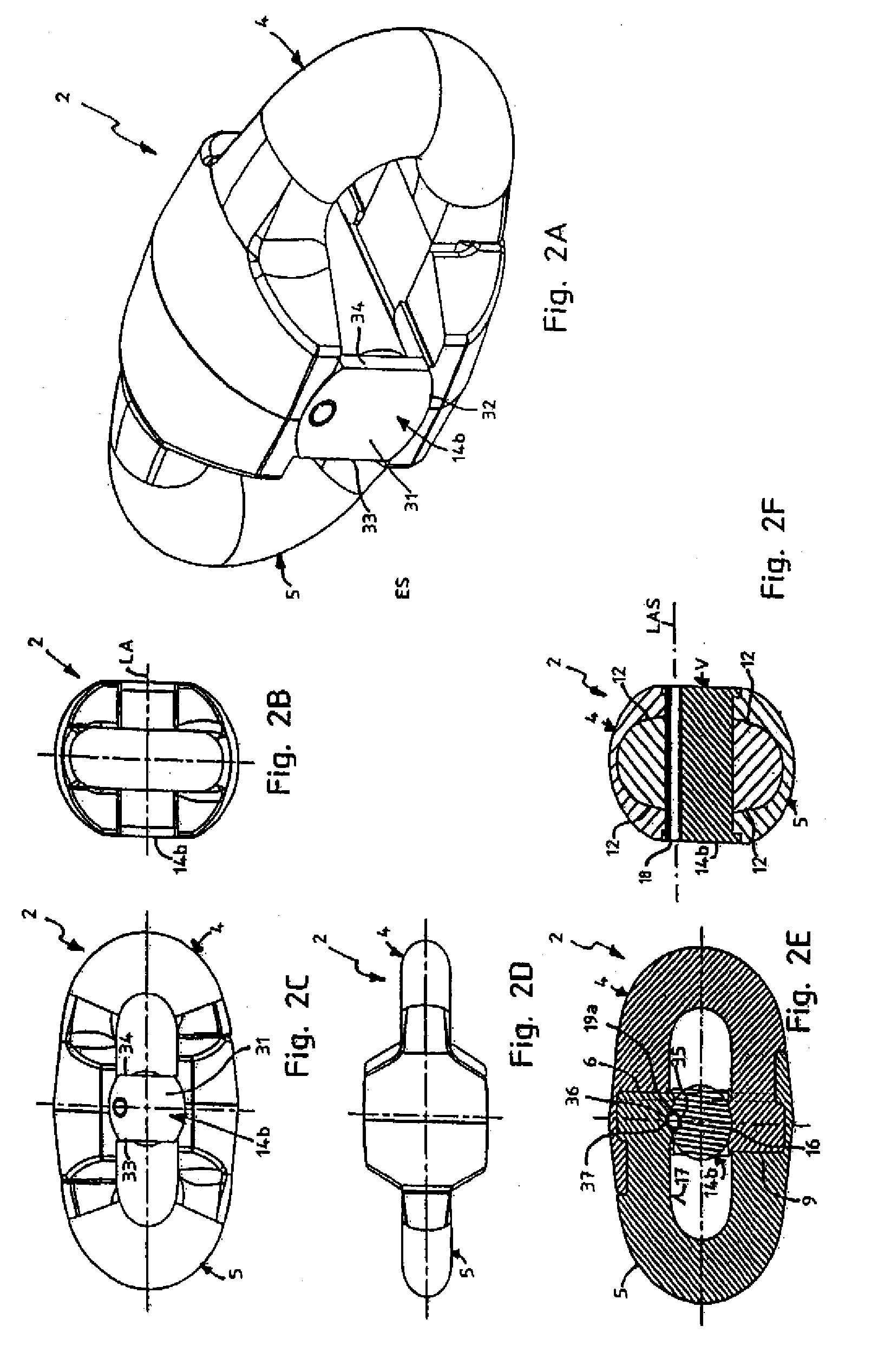
[0029]In the Figures, the chain connecting links in accordance with the invention have the reference numerals 1-3.
[0030]Each chain connecting link 1-3 of the FIGS. 1A to 3F has two equal link brackets 4, 5 which are coupled via their limbs. The link brackets 4, 5 are identical in all Figures. In addition, a limb 6 of each link bracket 4, 5 has a neck section 7 and a pin 8 which is thicker than the neck section 7. A corresponding neck recess 10 and a corresponding pin recess 11 are provided at the other limb 9 of the link bracket 4, 5. In accordance with the invention, conically configured flank surfaces 12 with respect to the vertical central longitudinal plane MLE of the pins 8 are provided at each pin 8 and at each pin recess 11 (see also FIGS. 4 and 5). Furthermore, the length L of the limb 6 is dimensioned such that the central transversal plane MQE of the chain connecting link 1-3 intersects the pins 8.
[0031]The link brackets 4, 5 are made of a suitable steel material by a for...
PUM
 Abstract
Description
Claims
Application Information