Thin film trough solar collector

a solar collector and thin film technology, applied in the direction of heat collector mounting/support, hybrid energy generation, lighting and heating apparatus, etc., can solve the problem that the tracking system of the suncone does not provide rigidity to the reflective surface geometries

Inactive Publication Date: 2011-11-15
PRUEITT FAMILY TRUST S PRUEITT TRUSTEE
View PDF38 Cites 33 Cited by
  • Summary
  • Abstract
  • Description
  • Claims
  • Application Information

AI Technical Summary

Benefits of technology

[0005]This invention, called “Suntrof” herein, is a design for a solar trough collector which has the target fluid pipe deep within the cavity formed by a parabolic reflector. The reflector is an aluminized plastic film or other flexible reflective material, which is held in place by being stretched horizontally (longitudinally) between rigid ribs and cemented to the inside of the ribs. A protective sheet of tough plastic film is cemented to the outside of the ribs to prevent wind from hitting the reflective film. The ribs can be metal or fiber-reinforced plastic and can be molded in a factory inexpensively.
[0006]Since many of the aluminized plastic films have high tensile strength, if a sheet of the film is stretched tightly between two curved ribs, the film between the ribs will have a strong tendency to maintain the same curvature as the ribs over the whole length of the film. The tension of the sheet is transmitted from rib to rib until the sheet reaches the end of the trough, where the force of the tension is countered by a rigid end framework. By this means, the ribs do not have to sustain any large lateral or longitudinal forces.

Problems solved by technology

But the major difference is that the Suntrof tracking system is designed to provide rigidity to the troughs, whereas the tracking system of Suncone does not provide rigidity to the reflective surface geometries.

Method used


Image

  • Thin film trough solar collector
  • Thin film trough solar collector
  • Thin film trough solar collector

Examples


Embodiment Construction

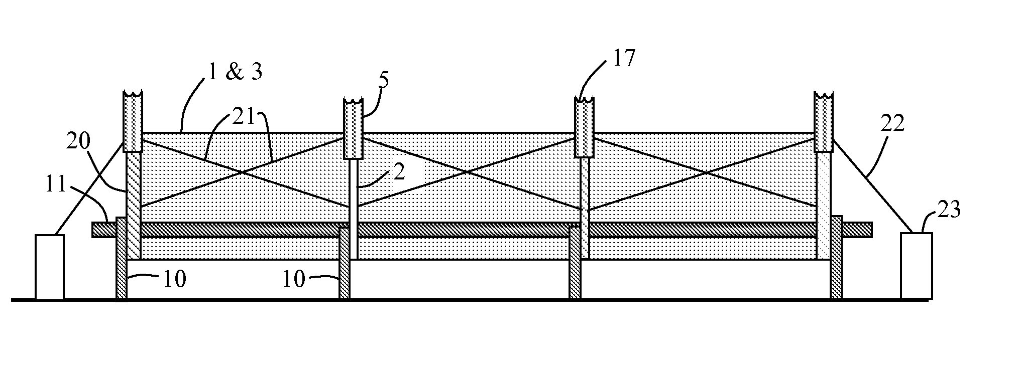
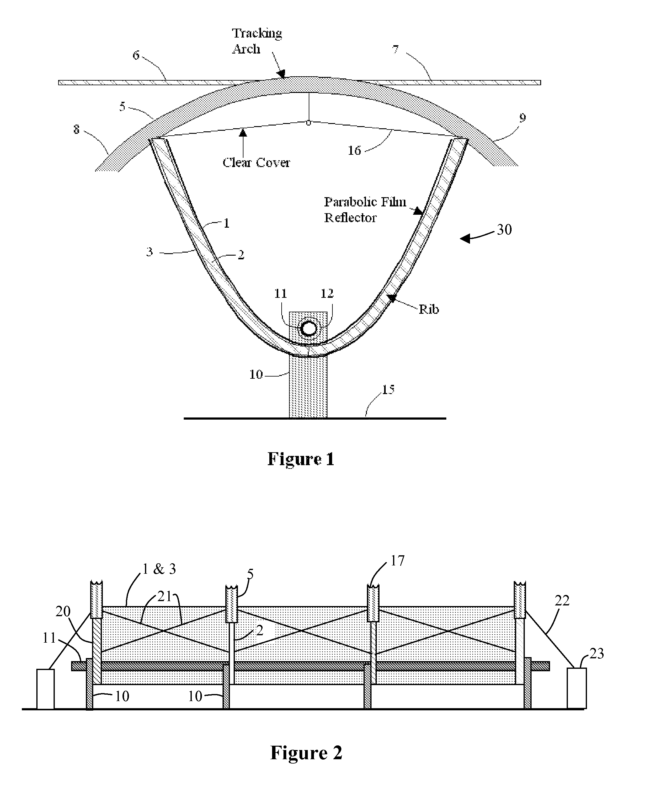
[0022]FIG. 1 is a schematic drawing of an end-view of the trough. FIG. 2 shows a side view of a short trough. Actually a trough may be quite long, and there may be many ribs distributed periodically along the trough.

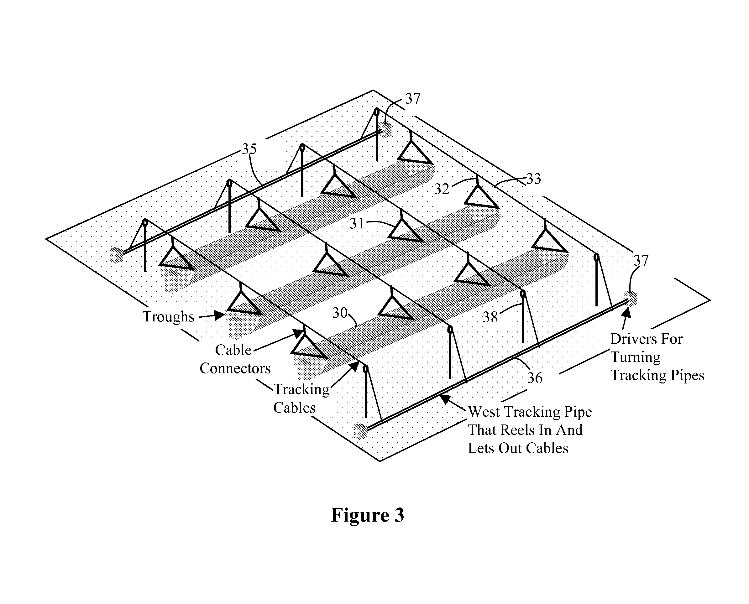
[0023]An important feature of this invention is that the whole trough is held rigid by the tracking cable system. At first, one might think that a long trough system built with lightweight plastic components would tend to twist along its length. That is, parts of it would point in different directions. But the tracking cable system is attached to the tracking arch 5, and that provides it with a long lever arm that pivots about the fluid pipe 11. Even a small cable can hold the system rigid in windy conditions, due to the long lever arm. Archimedes said, “Give me a lever long enough and a fulcrum on which to place it, and I shall move the world.” The ribs 2 and the tracking arches 5 form levers that rotate the trough from the top, rather than having the trough rotated fro...


PUM


Abstract

This invention is a trough solar collector that uses inexpensive aluminized plastic films as the reflecting surface. The films are held in proper shape by stretching them between rigid ribs that are spaced apart along the length of the collector. The structure of the trough is held rigid by a unique sun-tracking system that not only guides a whole of array of troughs on a field to point them toward the sun, but also maintains the whole length of each trough in rigid configuration. It is not necessary to extend rigid metal beams along the trough to maintain the rigidity of the trough. Small-diameter cables are wrapped around rotatable pipes that extend along the east and west sides of the field. The cables extend over the field of the troughs and are attached to connecting points above the troughs in such a way that when the rotatable pipes rotate, the cables move, the troughs move with them, and the cables provide the rigidity of the troughs. The troughs are supported by support posts that are driven into the ground. Since the support posts do not have to supply torque to rotate the troughs, no concrete foundations are necessary.

Description

CROSS-REFERENCE TO RELATED APPLICATION[0001]This claims priority to and the benefit of Provisional U.S. Patent Application Ser. No. 60 / 744,675, filed Apr. 12, 2006, the entirety of which is hereby incorporated herein by reference.BACKGROUND OF THE INVENTION[0002]Regular parabolic trough solar collectors are typically built with rugged structural members to provide rigidity so that when one part of the trough is rotated by a sun-tracking mechanism, the whole trough rotates together. The parabolic reflectors are typically glass or highly polished metal. U.S. Pat. Nos. 4,114,694 and 5,058,565 show trough structures that can be rotated by external means, but the troughs have to be rotationally rigid.[0003]The rigid structures of these troughs are expensive, and the reflecting surfaces are expensive.[0004]The tubes that carry the cooling fluid are typically located somewhat above the parabolic reflector. These designs are typically quite sensitive to the accuracy of the sun-tracking syst...

Claims


Application Information

Patent Timeline
Patent Type & Authority Patents(United States)
IPC IPC(8): F24J2/12F24J2/10F24S23/70F24S23/71F24S50/20
CPCF24J2/12F24J2/38F24J2/541F24J2/523F24J2002/5458Y02E10/42Y02E10/47F24S23/71F24S50/20F24S2030/133F24S30/425F24S25/10F24S23/74Y02E10/52Y02E10/60H02S20/32H02S40/22H02S40/44Y02E10/40
Inventor PRUEITT, MELVIN L.
Owner PRUEITT FAMILY TRUST S PRUEITT TRUSTEE
Why Eureka
Try Eureka