Safety mechanism for laminate battery

a safety mechanism and laminate battery technology, applied in the direction of secondary cell servicing/maintenance, cell components, grouping of flat cells, etc., can solve the problem of unthinkable application of such vents to laminate batteries, and achieve the effect of improving the safety features of the exterior case, preventing expansive deformation of the laminate battery, and improving the operation stability of the safety ven

Inactive Publication Date: 2011-11-15
PANASONIC CORP
View PDF26 Cites 13 Cited by
  • Summary
  • Abstract
  • Description
  • Claims
  • Application Information

AI Technical Summary

Benefits of technology

[0013]Exterior cases of laminate batteries, incidentally, have a low pressure resistance of about 1 MPa as compared to metal battery cases. The internal pressure could rise to as high as 0.3 MPa during charging or discharging even in normal use condition and the safety vent should preferably be actuated at about 0.4 to 0.7 MPa, more preferably at about 0.5 MPa. The tolerance range of variation in valve operating pressure must be about ±0.05 MPa. Accordingly, it is desirable to provide a safety vent for laminate batteries that can operate at the above low pressure with high precision and that have a low-cost configuration.
[0040]In this laminate battery, a pair of connection terminals respectively connected to both ends of the electrode plate group may be provided such that they protrude from the exterior case through the bonded part on one side of the exterior case. By providing the protrusion that has the exhaust hole on the same side as these connection terminals, the battery configuration can be made compact and inexpensive.

Problems solved by technology

Application of such vents to laminate batteries is unthinkable because of large functional difference, and of the inevitable large difference in configuration, between the laminate sheet exterior case of the laminate battery and the metal battery case.

Method used


Image

  • Safety mechanism for laminate battery
  • Safety mechanism for laminate battery
  • Safety mechanism for laminate battery

Examples


first embodiment

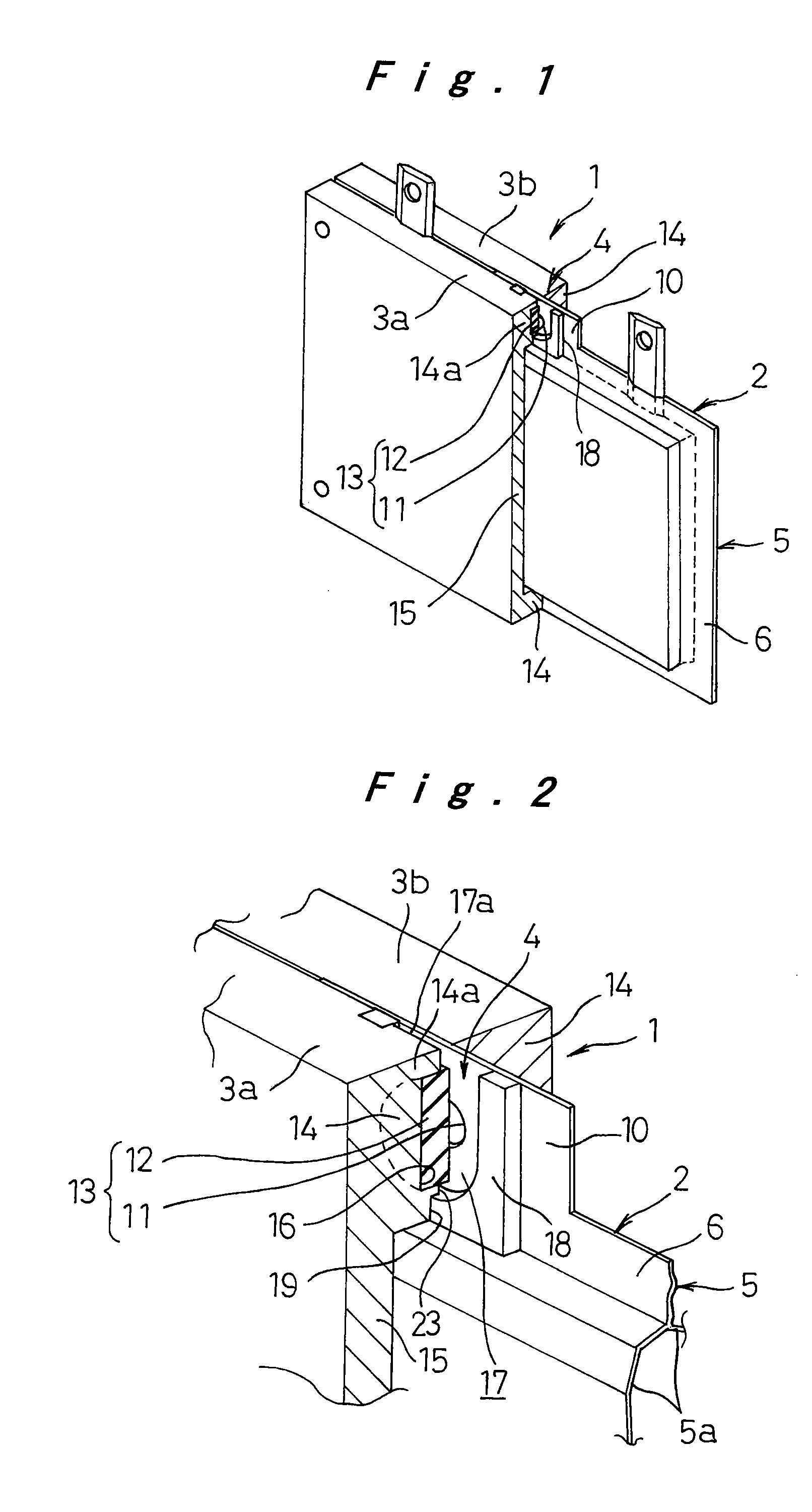
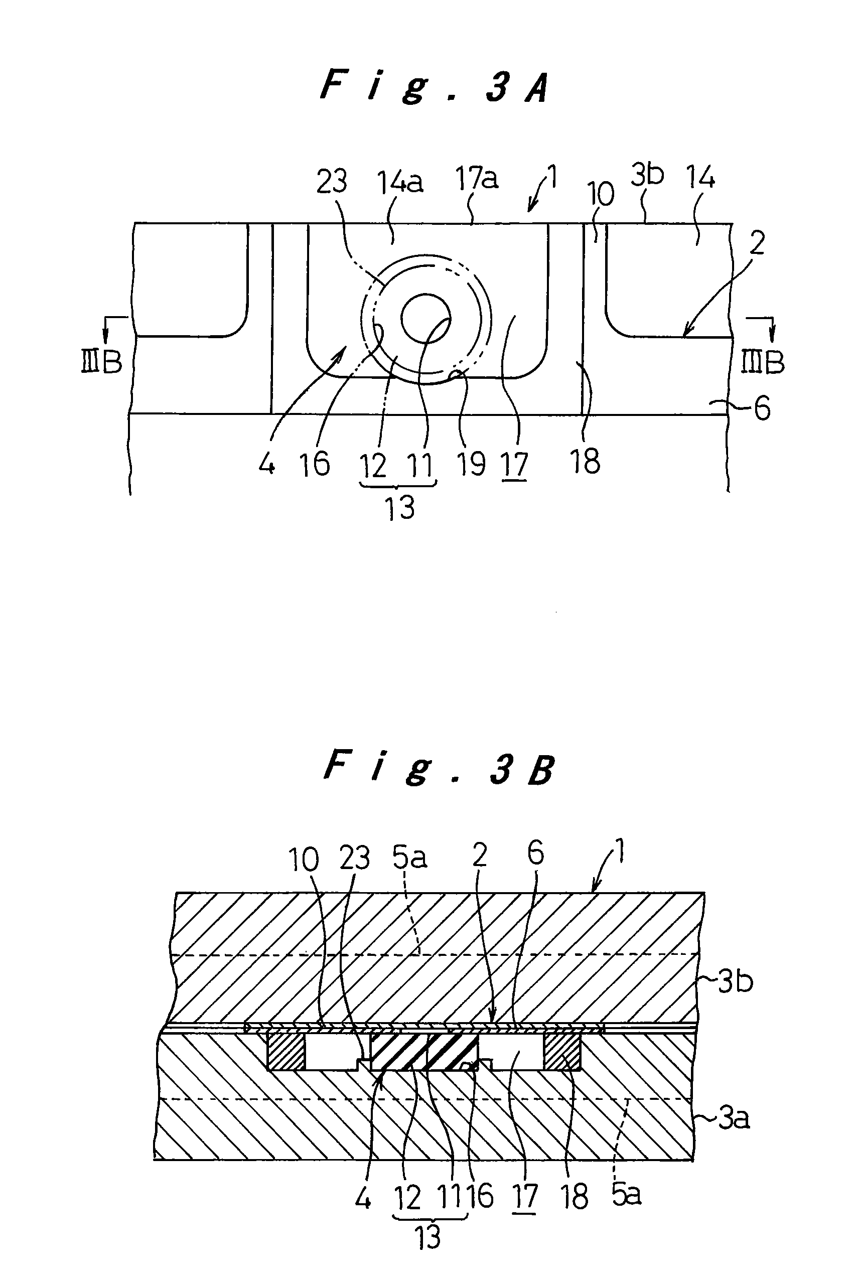
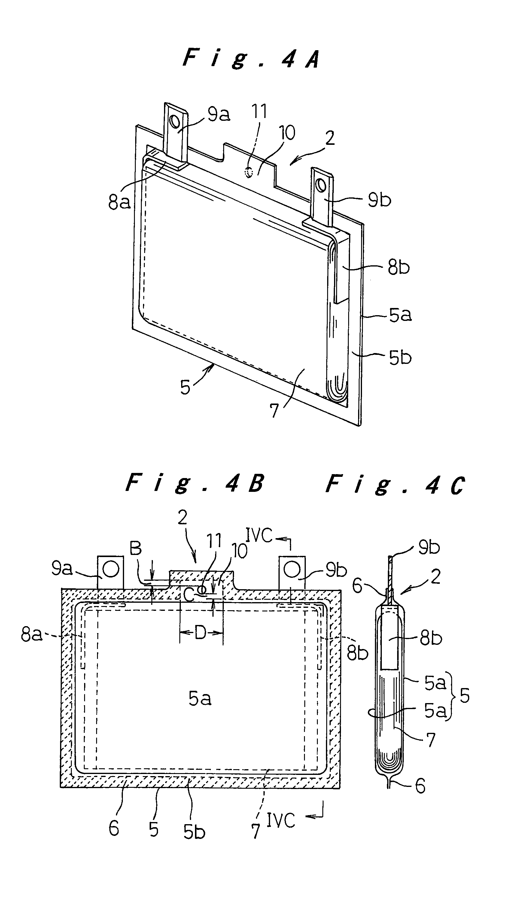
[0058]Embodiments of the present invention will be hereinafter described with reference to the drawings. FIG. 1 is a partly broken perspective view of a laminate battery unit 1 to which the safety mechanism for laminate batteries according to the present invention is adopted. FIG. 2 is an enlarged, partly broken perspective view of major parts of FIG. 1. FIG. 3A is a front view, partly removed, of the laminate battery unit 1, and FIG. 3B is a cross section taken along the line IIIB-IIIB of FIG. 3A. The laminate battery unit 1 is made up of a flat laminate battery 2, which includes a lithium ion battery, a pair of frame plates 3a and 3b that bind the laminate battery 2 and restrict its expansion resulting from a pressure build-up, and a safety mechanism 4 attached to the laminate battery 2 for exhausting the gas generated inside to the outside when the internal pressure of the laminate battery 2 rises to a predetermined level.

[0059]The laminate battery 2 will be described first with ...

seventh embodiment

[0096]FIG. 13 through FIG. 15A, and FIG. 15B illustrate the laminate battery unit 1 to which the safety mechanism for laminate batteries according to the present invention is adopted. FIG. 13 is a partly broken perspective view, FIG. 14 is an enlarged perspective view of major parts of FIG. 13, FIG. 15A is a front view, partly removed, of major parts, and FIG. 15B is a cross section taken along the line XVB-XVB of FIG. 15A. In these drawings, elements that are the same as or substantially equivalent to those of FIG. 1 through FIG. 3A, and FIG. 3B, are given the same reference numerals to avoid repetition of description.

[0097]FIG. 13 through FIG. 15A and FIG. 15B correspond respectively to FIG. 1 through FIG. 3A, and FIG. 3B.

[0098]The laminate battery unit 1, similarly to the first embodiment, is made up of a flat laminate battery 2, which consists of a lithium ion battery, a pair of frame plates 3a and 3b that form a holder for restricting the laminate battery 2 so as to restrict it...


PUM

PropertyMeasurementUnit
distanceaaaaaaaaaa
distanceaaaaaaaaaa
compression ratioaaaaaaaaaa

Abstract

A safety mechanism for a laminate battery. An exterior case (5) consists of two molded sheets (5a) made of laminate sheets, superposed upon one another, and bonded together around the outer edges. The exterior case has a protrusion (10) that communicates with the interior of the exterior case and protrudes outwardly from one side. A safety vent (13) is made up of an exhaust hole (11) formed in at lease one of the two molded sheets (5a) in the protrusion (10), and a valve element (12) making elastic pressure contact with the edge of the exhaust hole (11) to seal it. The safety mechanism does not operate within the range of internal pressure variation during normal use, but operates reliably at a time point when a predetermined valve operating pressure is reached to release a necessary amount of gas to the outside, this valve operating pressure being within the safe range relative to the pressure resistance of the exterior case (5) made of laminate sheets. Also, the safety vent configuration enables a reduction in production cost.

Description

RELATED APPLICATIONS[0001]This application is the U.S. National Phase under 35 U.S.C. §371 of International Application No. PCT / JP2006 / 309937 filed on May 18, 2006, which in turn claims the benefit of Japanese Patent Application No. 2005-149881, filed on May 23, 2005, Japanese Patent Application No. 2005-319295, filed on Nov. 2, 2005, Japanese Patent Application No. 2005-327110, filed on Nov. 11, 2005,and Japanese Patent Application No. 2006-027141, filed on Feb. 3, 2006, the disclosures of which Applications are incorporated by reference herein.TECHNICAL FIELD[0002]The present invention relates to a safety mechanism for a laminate battery in which an electrode plate group and an electrolyte are encased in an exterior case made of laminate sheets, the safety mechanism being provided for releasing generated gas to the outside when an internal pressure of the battery rises to a predetermined level.BACKGROUND ART[0003]Conventionally, lithium ion batteries and the like are commonly conf...

Claims


Application Information

Patent Timeline
Patent Type & Authority Patents(United States)
IPC IPC(8): H01M2/08H01M2/12H01M50/105H01M50/202H01M50/211H01M50/242H01M50/571
CPCH01M2/1077H01M2/12H01M2/1229H01M6/46H01M2/1223H01M2/0207H01M10/0525Y02E60/10H01M50/317H01M50/325H01M50/30H01M50/105H01M50/202H01M50/242H01M50/211H01M50/183
Inventor MIYAHISA, MASAHARUOHSAWA, YOSHIKIHATANAKA, TSUYOSHIYAMASAKI, YASUHIKO
Owner PANASONIC CORP
Why Eureka
Try Eureka