
Clip and hanger with the same

a technology of clip and hanger, applied in the direction of snap fasteners, clothes clips, buckles, etc., can solve the problems of difficult to remove clothing articles from clips, marks at the portions, and clothing articles are likely to fall off, so as to suppress the formation of marks

Active Publication Date: 2011-11-22
TAYA CO LTD
View PDF18 Cites 11 Cited by
  • Summary
  • Abstract
  • Description
  • Claims
  • Application Information

AI Technical Summary

Benefits of technology

[0010]The present invention provides thus a clip whose clamping force increases when an object clamped by the clip is pulled away from the clip. The clip according to the present invention can effectively prevent a clothing article from coming off the clip. In addition, the clamping force of the clip of the present invention can be made to increase temporarily, which as a result allows sufficiently suppressing formation of marks on the portions of the clothing article clamped by the clip. The present invention provides also a hanger comprising the above-described clip.

Problems solved by technology

The clothing article is likely to fall off when using a clip having insufficient clothing clamping force.
On the other hand, using a clip having an excessive clothing clamping force gives rise to marks at the portions of the clothing article clamped by the clip, while making it harder to remove the clothing article from the clip.

Method used


Image

  • Clip and hanger with the same
  • Clip and hanger with the same
  • Clip and hanger with the same

Examples


first embodiment

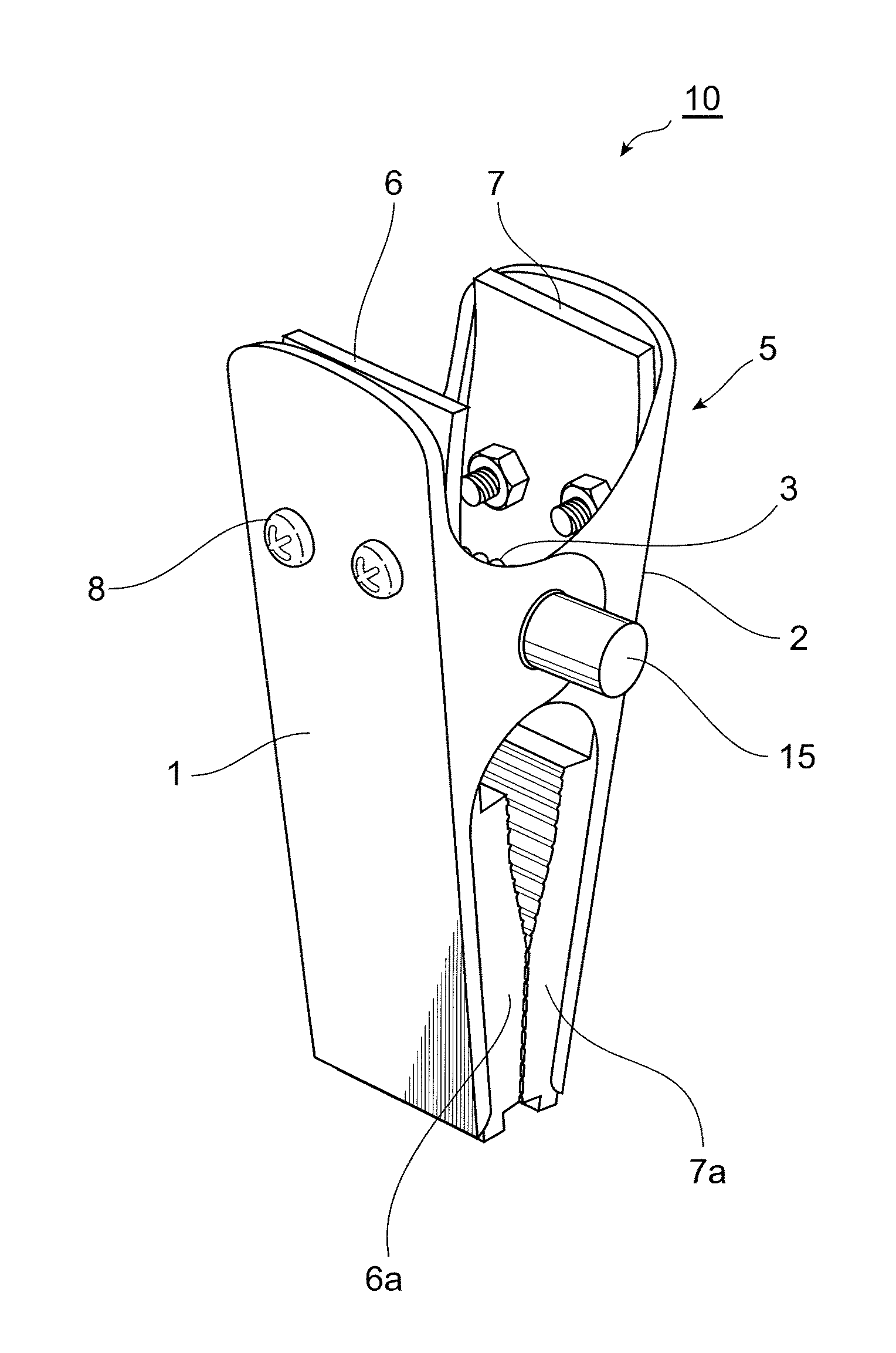
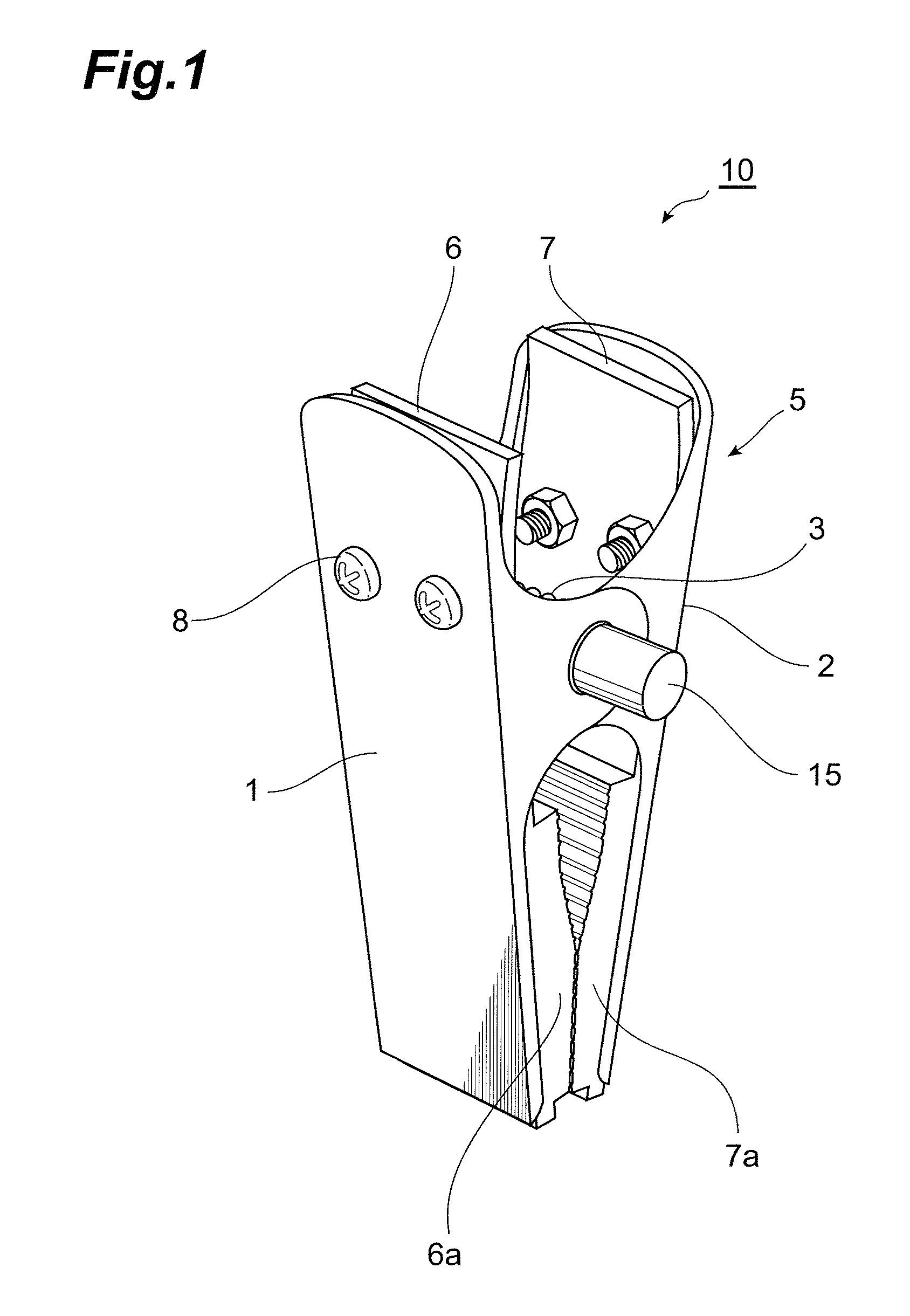
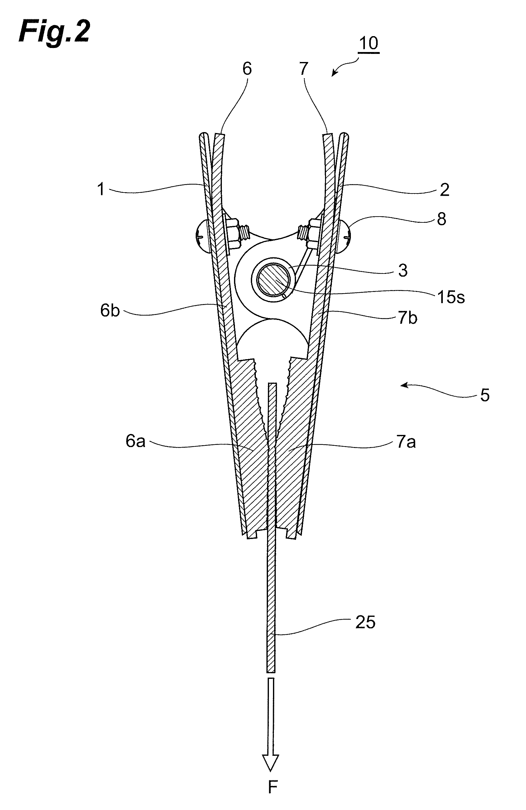
[0031]FIG. 1 is a perspective-view diagram illustrating the clip of the present invention. FIG. 2 is a cross-sectional diagram of a clip 10 according to the present embodiment, when clamping an object. The clip 10 comprises a clip body 5, in which a pair of clip members 1, 2 are pivotally connected to each other, and a pair of clamping force increasing members 6, 7 that increases the clamping force of the clip body 5. The clamping force increasing member 6 has a slip prevention section 6a disposed between the pair of clip members 1, 2, and a transmission section 6b for transmitting to the clip member 1 the friction force that the slip prevention section 6a receives from an object 25. Similarly, the clamping force increasing member 7 has a slip prevention section 7a disposed between the pair of clip members 1, 2, and a transmission section 7b for transmitting to the clip member 2 the friction force that the slip prevention section 7a receives from an object 25. The clamping force inc...

second embodiment

[0039]FIG. 4 is a perspective-view diagram illustrating the clip of the present invention, and FIG. 5 is a cross-sectional diagram of a clip 20 according to the embodiment. A pair of clamping force increasing members 26, 27 of a clip 20 according to the present embodiment has slip prevention sections 26a, 27a formed so as to cover part of the leading ends of the clip members 1, 2. Except for the clamping force increasing members, the clip 20 can be constructed in the same way as the clip 10.

third embodiment

[0040]FIG. 6 is a cross-sectional diagram illustrating the clip of the present invention. A pair of clamping force increasing members 36, 37 of a clip 30 according to the present embodiment comprises, on the base end sides of transmission sections 36b, 37b, fixing means 36c, 37c formed so as to cover part of the base end sides of the clip members 1, 2. Otherwise, the constitution of the clip 30 is identical to that of the clip 20. As fixing means there may be respectively provided, on the clamping force increasing members 36, 37, band-like members 36d, 37d that are fastened to rising sections 1a, 2a in the central direction of the clip members having openings for inserting the core rod 15, as illustrated in FIG. 7.


PUM


Abstract

A clip for clamping an object (25) has a clip body (5) where a pair of clip members (1, 2) are pivotally connected to each other, clamping force increasing members (6, 7) for increasing a clamping force of the clip body; and fixing means (8) for supporting the clamping force increasing members on the clip body. The clamping force increasing members have slip prevention sections (6a, 7a) disposed between leading ends of the clip body and clamped by the clip body together with the object, and have also transmission sections (6b, 7b) connected to the slip prevention sections and fixed to the clip members by the fixing means, to cause the friction force that the slip prevention sections receive from the object to be transmitted to the clip body.

Description

BACKGROUND OF THE INVENTION[0001]1. Field of Invention[0002]The present invention relates to a clip and to a hanger comprising the clip.[0003]2. Description of the Related Prior Art[0004]Clothing articles such as skirts, trousers and the like are transported and displayed while clamped by clips provided in hangers. The clothing article is likely to fall off when using a clip having insufficient clothing clamping force. On the other hand, using a clip having an excessive clothing clamping force gives rise to marks at the portions of the clothing article clamped by the clip, while making it harder to remove the clothing article from the clip.[0005]Increasing the force with which the clothing article is clamped, and enlarging the surface area over which the clothing article and the clip come into contact, to increase the friction force therebetween, are known means for preventing the clothing article from falling off (see Patent document 1).[0006]Patent document 1: Japanese Unexamined ...

Claims


Application Information

Patent Timeline
Patent Type & Authority Patents(United States)
IPC IPC(8): A41D27/22
CPCA47G25/485D06F55/02Y10T24/44017
Inventor SUGITA, HARUOSUGITA, KIYOSHI
Owner TAYA CO LTD
Learn More