Cutter device for a crushing machine

a crushing machine and cutter technology, applied in the field of cutter devices for crushing machines, to achieve the effect of saving manufacturing time, great precision, and being impossible to deform

Inactive Publication Date: 2011-11-22
CHANG YU CHUN
View PDF7 Cites 6 Cited by
  • Summary
  • Abstract
  • Description
  • Claims
  • Application Information

AI Technical Summary

Benefits of technology

[0007]The rotary cutter base and the fixing bases in the present invention are formed integral so they can be shaped with great precision and impossible to be deformed, thus saving time in manufacturing and facilitating the cutters to be locked on the fixing bases. Further, each cutter has four cutting edges extending toward the center to form a bulging portion for thickening the cutter, thus able to prolong their service life and lower equipment cost. Furthermore, the annular ribs are respectively formed with arcuate cross sections and the flat cut surfaces are respectively provided with a first flat cut portion and a second flat cut portion, all helpful to carry quantities of wood chips. Moreover, the cross section of each cutting side is formed with a double-curved surface for facilitating wood chips to be cast out and speeding up chip cutting work, and the fixing bases are respectively formed integrally on the flat cut surface of the annular rib.

Problems solved by technology

Thus, when the cutter bases 13 are welded, the rollers 11 of the cutter base body 10 are easily deformed due to heat produced by welding, likely to result in inaccuracy when the cutter base body 10 is to be assembled later on.

Method used


Image

  • Cutter device for a crushing machine
  • Cutter device for a crushing machine
  • Cutter device for a crushing machine

Examples


Embodiment Construction

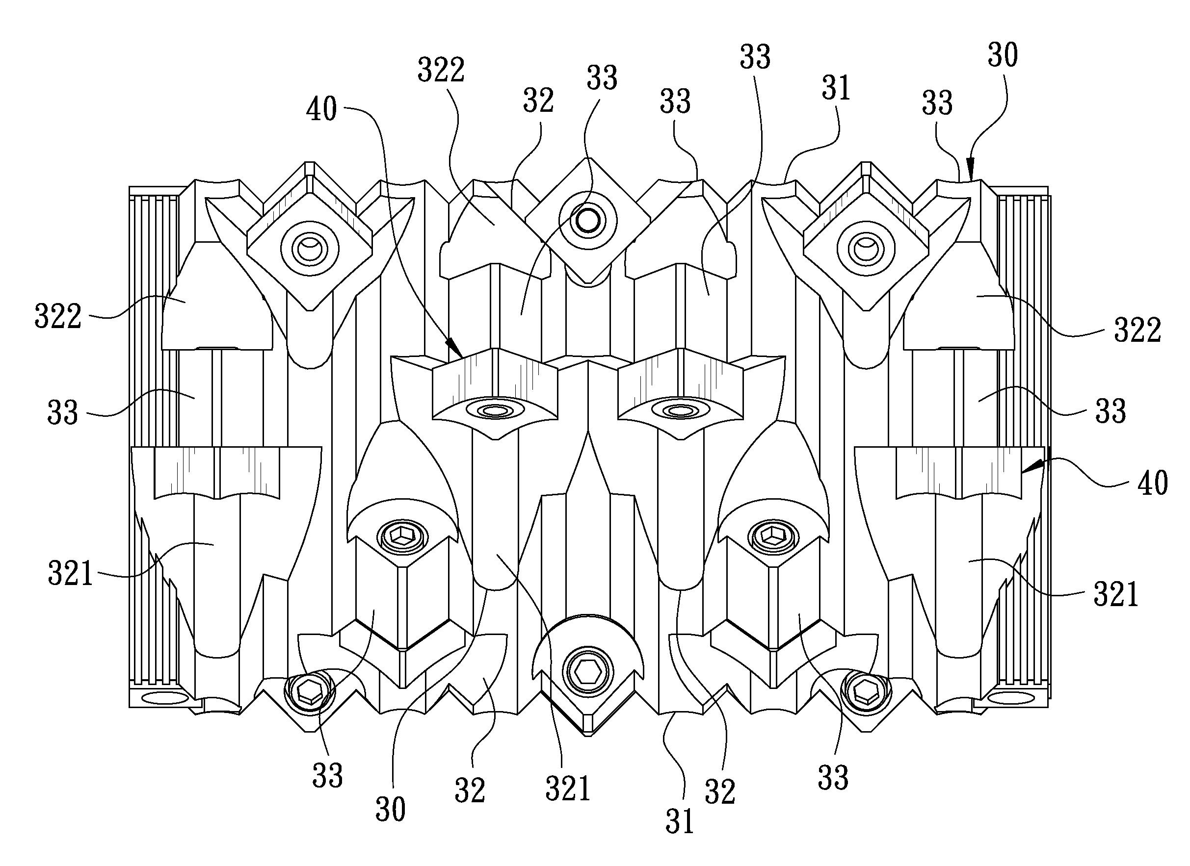
[0019]A preferred embodiment of a cutter device for a crushing machine 100 in the present invention, as shown in FIG. 4, is installed in the interior of the crushing machine 100 for crushing timber conveyed by a conveyer device and includes a rotary cutter base body 30 and a plurality of cutters 40 combined together.

[0020]The rotary cutter base body 30, referring to FIGS. 5, 6 and 7, is formed integral and able to be rotated axially. The rotary cutter base body 30 has an outer peripheral surface axially and equidistantly formed with a plurality of annular ribs 31 respectively and diametrically provided with plural flat cut surfaces 32 along the rotary cutter base body 30, and each flat cut surface 32 is divided into a first flat cut portion 321 and a second cut portion 322 and disposed with a fixing base 33 with a fixing hole 331 and, with the fixing base 33 serving as boundary and provided with a fixing hole 331. The annular rib 31 is generally formed with an M-shaped arcuate cross...


PUM


Abstract

A cutter device for a crushing machine includes a rotary cutter base body and plural cutters. The rotary cutter base body is formed integral and has an outer peripheral side axially and equidistantly formed with plural annular ribs respectively provided with plural flat cut surfaces. Each flat cut surface is formed integral with a protruding fixing base with a fixing hole for locking each cutter on the fixing base. Each cutter body is formed with a cutting side disposed with at least four arcuate cutting edges extending toward the center to form a bulging portion, with the cross section of the cutter side formed with a double-curved surface for thickening the cutter to prolong its service life. The fixing bases are formed integrally with the rotary cutter base body to increase their strength.

Description

RELATED APPLICATION[0001]The present application is a continuation-in-part application and claims benefits of a U.S. patent application Ser. No. 11 / 768,285 filed on Jun. 26, 2007, now abandoned.BACKGROUND OF THE INVENTION[0002]1. Field of the Invention[0003]This invention relates to a cutter device for a crushing machine and particularly relates to a cutter device formed integrally and employed for crushing wood chips or plastic material. The invention is a continuation-in-part application of the U.S. patent application Ser. No. 11 / 768,285.[0004]2. Description of the Prior Art[0005]The cutter device of a conventional crushing machine, as shown in FIGS. 1, 2 and 3, includes a cutter base body 10 and a plurality of cutters 20. The cutter base body 10 consists of a plurality of rollers 11 arranged successively. The peripheral sides of the plurality of rollers 11 are respectively and diametrically formed with axially successive arch ribs 12. Each arch rib 12 has a triangular cross secti...

Claims


Application Information

Patent Timeline
Patent Type & Authority Patents(United States)
IPC IPC(8): B02C18/16
CPCB02C18/145B02C18/146B02C18/18B02C18/184
Inventor CHANG, YU-CHUN
Owner CHANG YU CHUN
Why Eureka
Try Eureka