
Method and apparatus for optimizing braking control during a threshold braking event

a braking control and threshold technology, applied in the direction of motor/generator/converter stoppers, dynamo-electric converter control, transportation and packaging, etc., can solve problems such as driveline disturbance, reduce stopping distances, and minimize such driveline disturbances.

Active Publication Date: 2011-11-22
GM GLOBAL TECH OPERATIONS LLC
View PDF6 Cites 37 Cited by
  • Summary
  • Abstract
  • Description
  • Claims
  • Application Information

AI Technical Summary

Benefits of technology

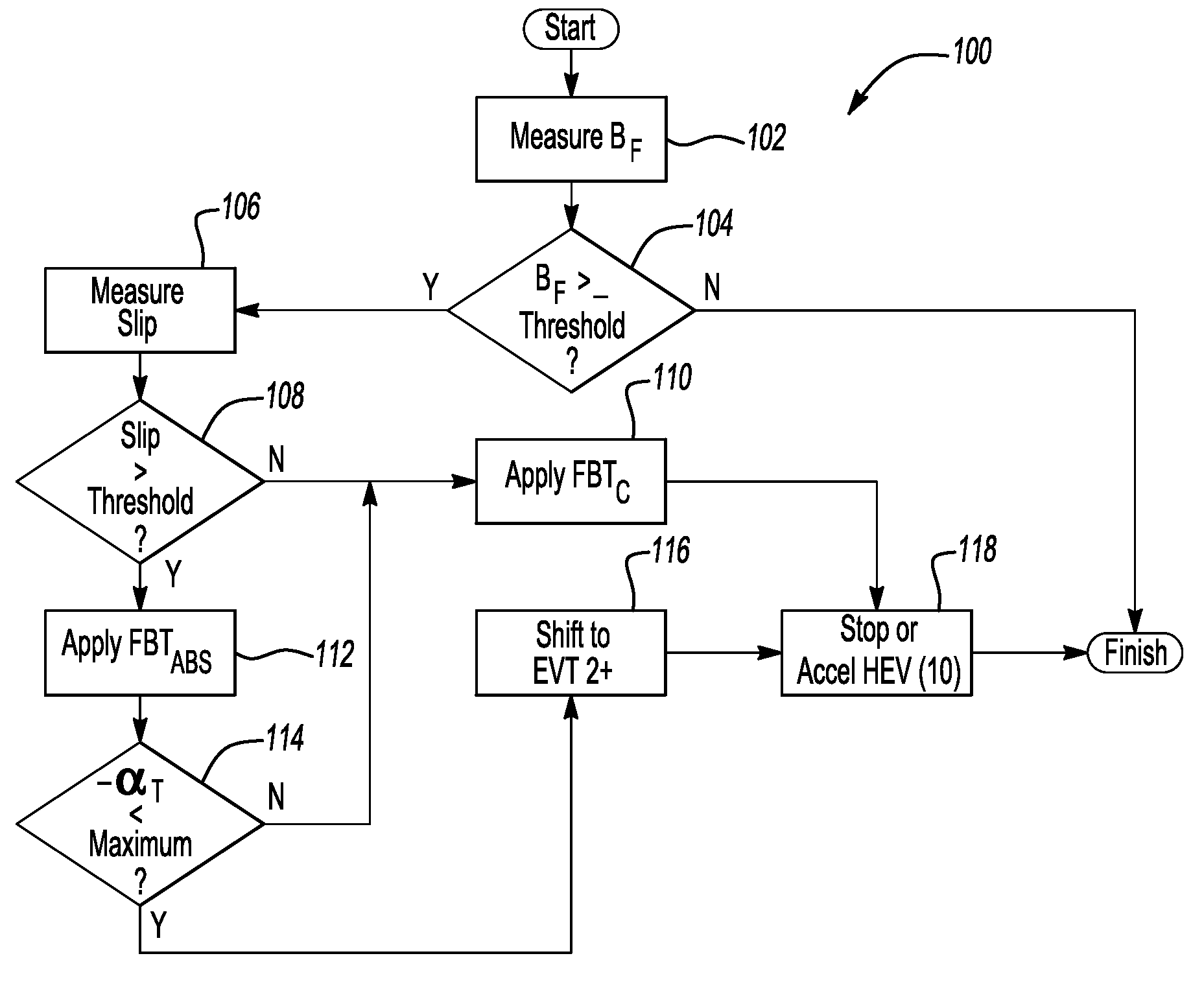
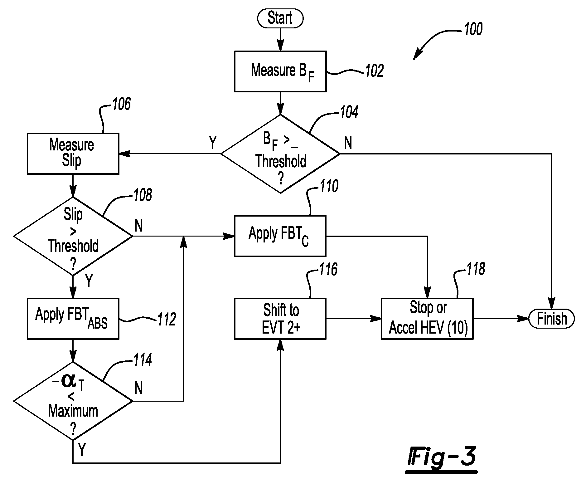
[0009]In order to minimize such driveline disturbances on low coefficient of friction surfaces, while at the same time reducing stopping distances on low-μ surfaces, the method of the invention is executed via the apparatus in order to automatically shift the EVT to a default higher speed / lower torque EVT mode, or to retain the EVT in the higher speed mode if already operating in this mode, whenever the threshold braking event is present. In this manner, the method and apparatus can temporarily override a main EVT shift control algorithm by commanding the EVT to shift to and / or remain in the higher speed / lower torque EVT mode for the duration of the threshold braking event. Reduced stopping distances in particular are provided optimizing brake pressure control of the drive wheels in the high speed / lower torque EVT mode. Lower driveline inertia allows the drive wheels to recover to vehicle speed more quickly after brake pressure is released during an ABS event, which allows the pressure to be reapplied more quickly, resulting in optimal braking efficiency.

Problems solved by technology

However, the ratio of a lowest speed / highest torque EVT mode is such that any resonance imparted by the rapid frictional brake pressure cycling occurring during an active ABS braking event can cause a driveline disturbance.

Method used


Image

  • Method and apparatus for optimizing braking control during a threshold braking event
  • Method and apparatus for optimizing braking control during a threshold braking event
  • Method and apparatus for optimizing braking control during a threshold braking event

Examples


Embodiment Construction

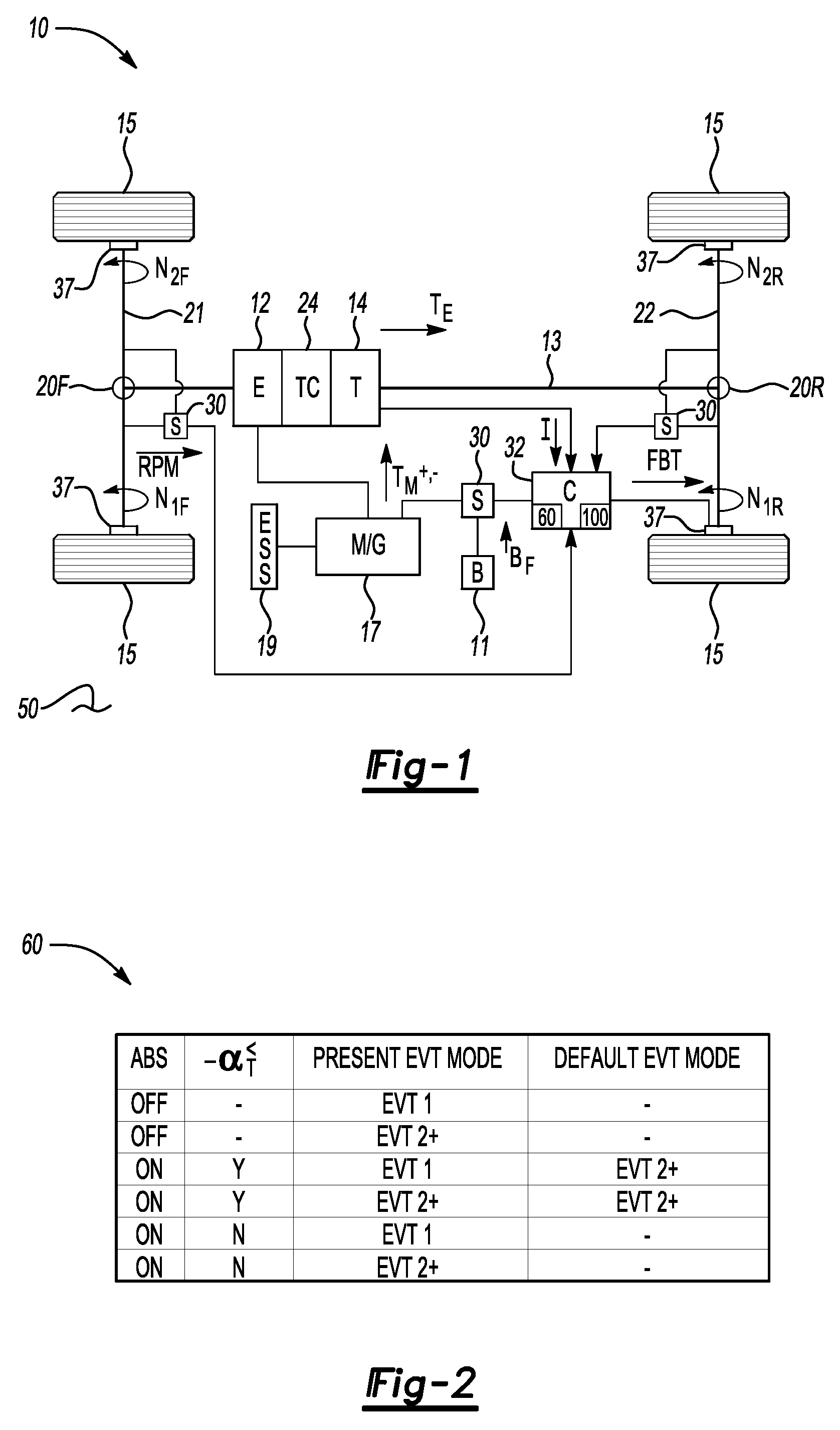
[0016]With reference to the Figures, wherein like reference numerals refer to like or similar components throughout the several figures, and beginning with FIG. 1, a hybrid electric vehicle (HEV) 10 is shown that includes an energy conversion system (E) 12, an electrical storage system (ESS) 19, and at least one electric motor / generator (M / G) 17. The energy conversion system 12 can be drivingly connected to an automatic transmission (T) 14 via a hydrodynamic torque converter assembly (TC) 24 as shown, via another torque transfer mechanism such as a clutch, or via a direct connection to a set of drive wheels 15. The HEV 10 includes an electronic control unit or controller 32 having an algorithm or method 100 as described below with reference to FIGS. 2 and 3.

[0017]The controller 32 refers broadly to a distributed or central control module, which can include such control modules and capabilities as might be necessary to operate the HEV 10 in the desired manner, including an engine con...


PUM


Abstract

A method minimizes a driveline vibration and reduces stopping distances in a hybrid electric vehicle (HEV) having a plurality of drive wheels, a friction braking system having antilock braking system (ABS) capability, and an electronically variable transmission (EVT) with two EVT modes. The method automatically shifts the EVT to a predetermined high speed / low torque EVT mode when the ABS is active and when a calibrated maximum deceleration rate is not exceeded. An HEV has a friction braking system with ABS capability and an EVT including a plurality of modes. A controller automatically activates the friction braking ABS in response to a threshold level of slip between the drive wheels and the road surface when the brake pedal is actuated. An algorithm automatically shifts the EVT into one of the high speed / low torque EVT modes when the ABS is activated and the calibrated maximum deceleration rate is not exceeded.

Description

TECHNICAL FIELD[0001]The present invention relates generally to a method and an apparatus for optimizing braking control of a vehicle, and in particular to reducing driveline vibration and stopping distances by automatically selecting or retaining a default transmission operating mode in a hybrid electric vehicle during a threshold braking event.BACKGROUND OF THE INVENTION[0002]A hybrid electric vehicle (HEV) selectively utilizes multiple sources of energy in order to improve overall fuel economy, as well as to reduce certain vehicle emissions. An HEV includes a rechargeable energy storage system (ESS), which is ordinarily configured as a battery or a battery pack having a relatively high energy density. The ESS is electrically connected to at least one of the multiple energy sources. The multiple energy sources most often include a gasoline, diesel, or alternative fuel internal combustion engine and at least one electric motor / generator. Other HEV designs may alternately employ a f...

Claims


Application Information

Patent Timeline
Patent Type & Authority Patents(United States)
IPC IPC(8): H02P3/04
CPCB60K6/365B60K6/547B60L7/18B60L7/26B60L15/2054B60W10/06B60W10/08B60W20/00B60K6/48Y10T477/393B60W2520/26Y02T10/6221Y02T10/6286Y02T10/7275Y10T477/373Y10T477/387Y10T477/24Y02T10/72Y02T10/62Y02T10/64B60W2520/28B60W2520/30B60W10/184B60W20/10
Inventor KRUEGER, ERIC E.MILLER, THOMAS S.HEAP, ANTHONY H.
Owner GM GLOBAL TECH OPERATIONS LLC
Learn More