Method and device for non destructive evaluation of defects in a metallic object

a technology of non-destructive evaluation and metallic objects, applied in the direction of material analysis by electric/magnetic means, measurement devices, instruments, etc., can solve the problem of limited signal-to-noise ratio

Active Publication Date: 2011-11-22
COMMISSARIAT A LENERGIE ATOMIQUE ET AUX ENERGIES ALTERNATIVES
View PDF9 Cites 43 Cited by
  • Summary
  • Abstract
  • Description
  • Claims
  • Application Information

AI Technical Summary

Benefits of technology

[0017]More specifically a main object of the present invention is to increase the signal-to-noise ratio and to get rid of the main fluctuations of sensors due for example to the temperature drift or to ageing.
[0020]The signal due to the eddy current is unambiguously different from the excitation signal and can therefore be highly amplified, thus increasing the signal-to-noise ratio.
[0021]A main advantage of the method according to the invention lies in the fact that it is possible to get rid of the main fluctuations of the magnetoresistive sensor due for example to the temperature drift or to the ageing. Furthermore, a lot of noise due to the electromagnetic interference (EMI) at the field emitter frequency may be avoided. This interference is due to the field induced by the emitter and preferentially appears for frequencies greater than 100 kHz.

Problems solved by technology

In all these cases, even if the sensitivity is increased, the sensor which might be either a coil or a magnetoresistive element, detects the signal of the eddy current at a frequency equal to the excitation coil's frequency, and is therefore limited in term of signal-to-noise ratio.

Method used


Image

  • Method and device for non destructive evaluation of defects in a metallic object
  • Method and device for non destructive evaluation of defects in a metallic object
  • Method and device for non destructive evaluation of defects in a metallic object

Examples


Embodiment Construction

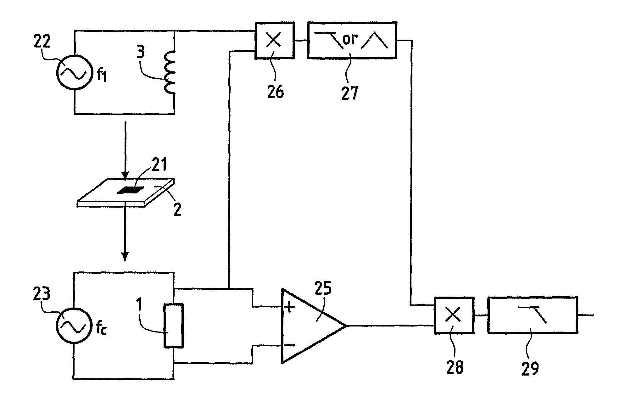
[0056]The invention essentially addresses a method which improves the signal-to-noise ratio of the detection of defects through measurement of eddy currents, by using a magnetoresistive sensor as an in situ demodulator.

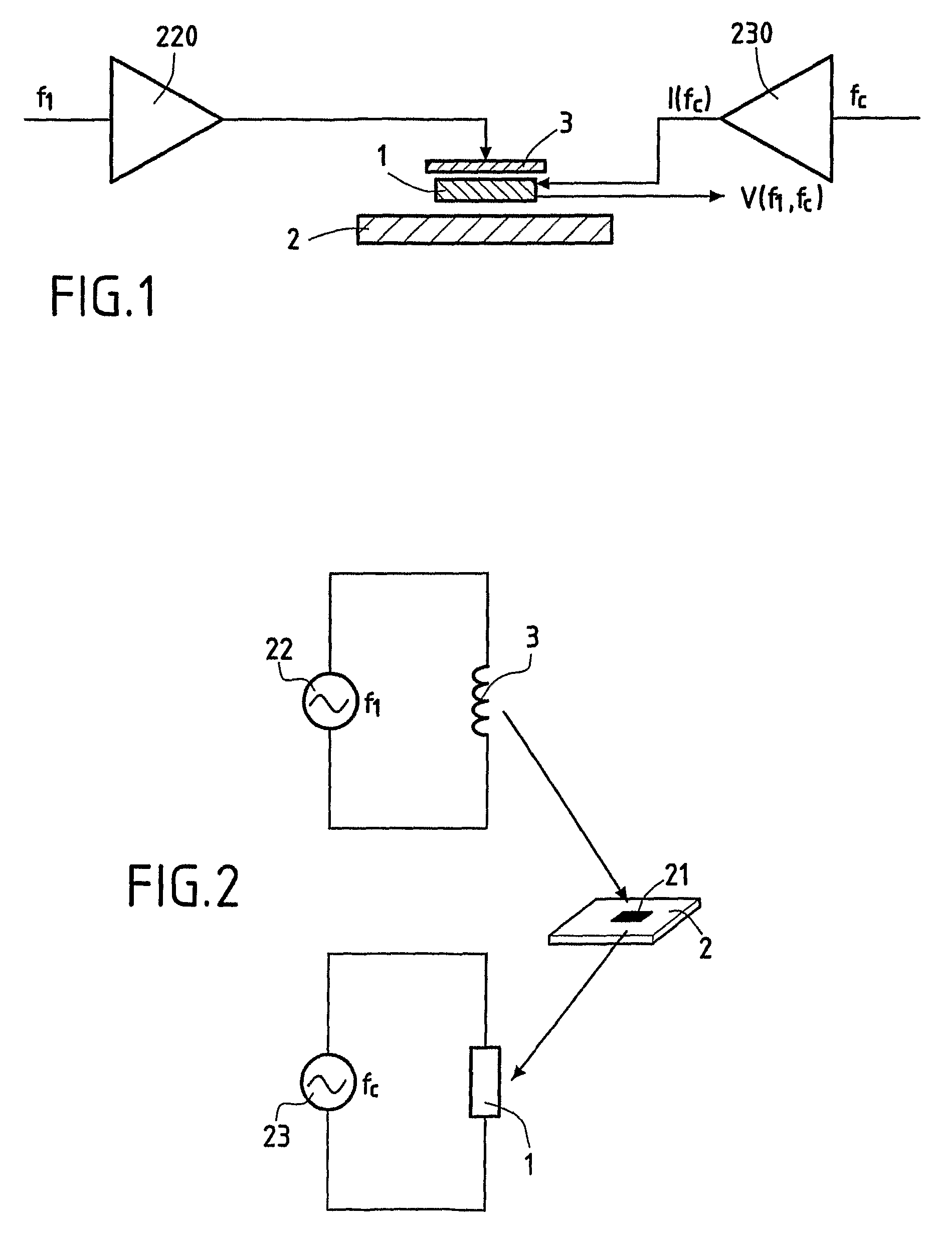
[0057]The principle of the measurement method will be explained hereafter with reference to FIG. 1.

[0058]An emitter 3, which can be a coil for instance, is fed through an amplifier 220 with an alternating current (AC) or radiofrequency (RF) field at a frequency f1. The emitter 3, which is located in close proximity to a metallic object 2 to be inspected, sends in turn the AC or RF field at the frequency f1 in the tested object 2. The object to be inspected 2 re-emits a signal at the frequency f1.

[0059]According to the invention a magnetoresistive (MR) sensor 1 is located in the vicinity of the object to be inspected 2 and is fed through an amplifier 230 with a radiofrequency current at a frequency fc which is different from the working frequency f1.

[0060]The MR sensor...


PUM

PropertyMeasurementUnit
frequencyaaaaaaaaaa
widthaaaaaaaaaa
widthaaaaaaaaaa

Abstract

A device for non destructive evaluation of defects in a metallic object (2) by eddy currents, comprises a field emitter (3) for emitting an alternating electromagnetic field at a first frequency fi in the neighborhood of the metallic object (2), and a magnetoresistive sensor (1) for detecting a response signal constituted by a return electromagnetic field which is re-emitted by eddy currents induced by the alternating electromagnetic field in the metallic object (2). The device further comprises: a driving circuit (230) for driving the magnetoresistive sensor (1) by a current at a second frequency fc which is different from the first frequency fi, so that the magnetoresistive sensor (1) acts as an in situ modulator; a detector for detecting a response signal between the terminals of the magnetoresistive sensor (1); a filter for filtering the response signal detected by the magnetoresistive sensor (1) to keep either the frequency sum (fi+fc) of the first and second frequencies or the frequency difference (fi−fc) of the first and second frequencies, and a processor for processing the filtered response signal and extract eddy current information on defects in the metallic object (2).

Description

[0001]This application is a §371 national phase filing of PCT / EP2006 / 002599 filed Feb. 24, 2006.BACKGROUND OF THE INVENTION[0002]1. Field of the Invention[0003]The present invention relates to a method and a device for non destructive evaluation of defects in a metallic object by eddy currents.[0004]The invention more specifically relates to a method for non destructive evaluation of defects in a metallic object by eddy currents, the method comprising the steps of emitting at least one alternating electromagnetic field at at least one first frequency fi in the neighbourhood of the metallic object and detecting through at least one magnetoresistive sensor a response signal constituted by a return electromagnetic field which is re-emitted by eddy currents induced by the alternating electromagnetic field in said metallic object.[0005]2. Description of the Related Art[0006]The technique of detection of defects in metallic objects by observation of the deformation of eddy currents lines ...

Claims


Application Information

Patent Timeline
Patent Type & Authority Patents(United States)
IPC IPC(8): G01N27/82G01R33/09
CPCG01N27/9046
Inventor FERMON, CLAUDEPANNETIER, MYRIAMBIZIERE, NICOLASVACHER, FRANCOISSOLLIER, THIERRY
Owner COMMISSARIAT A LENERGIE ATOMIQUE ET AUX ENERGIES ALTERNATIVES
Why Eureka
Try Eureka