
Method for functionally testing an ultrasonic sensor

a technology of ultrasonic sensor and functional testing, applied in the direction of transmission monitoring, instruments, measurement devices, etc., can solve problems such as undesirable effects, and achieve the effects of reducing measurement time, amplitude, and reducing signal duration

Inactive Publication Date: 2011-11-22
ROBERT BOSCH GMBH
View PDF13 Cites 9 Cited by
  • Summary
  • Abstract
  • Description
  • Claims
  • Application Information

AI Technical Summary

Benefits of technology

The present invention provides a method and device for functionally testing an ultrasonic sensor and measuring distance to objects using the sensor. The emitted signal is designed to be reflected by the ground, making it easy to test the sensor even if there are no obstacles in the vicinity of the vehicle. The test can be carried out even if the vehicle is not on a normal roadway surface. The method includes increasing the amplitude and duration of the emitted ultrasonic signal to acquire a reflection of the ground echo. The detection of the ground echo is important for ensuring the sensor is functioning properly. The method can also be used to evaluate the sensitivity of the sensor and detect critical states caused by contamination or poor sensor performance. The invention provides a reliable and efficient way to functionally test ultrasonic sensors and measure distance to objects.

Problems solved by technology

In general, this effect is undesirable, because reflections from the roadway surface may be erroneously interpreted as indicating the presence of an obstacle in the vicinity of the vehicle.

Method used


Image

  • Method for functionally testing an ultrasonic sensor
  • Method for functionally testing an ultrasonic sensor
  • Method for functionally testing an ultrasonic sensor

Examples


Embodiment Construction

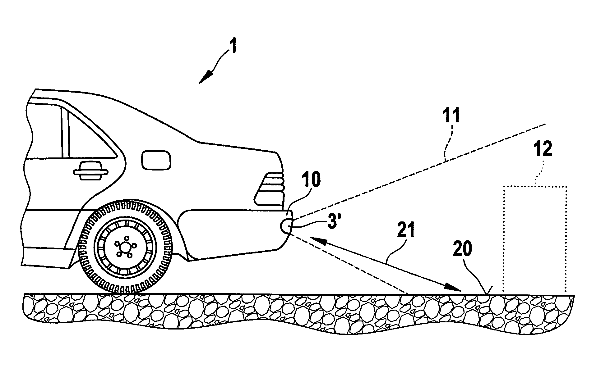
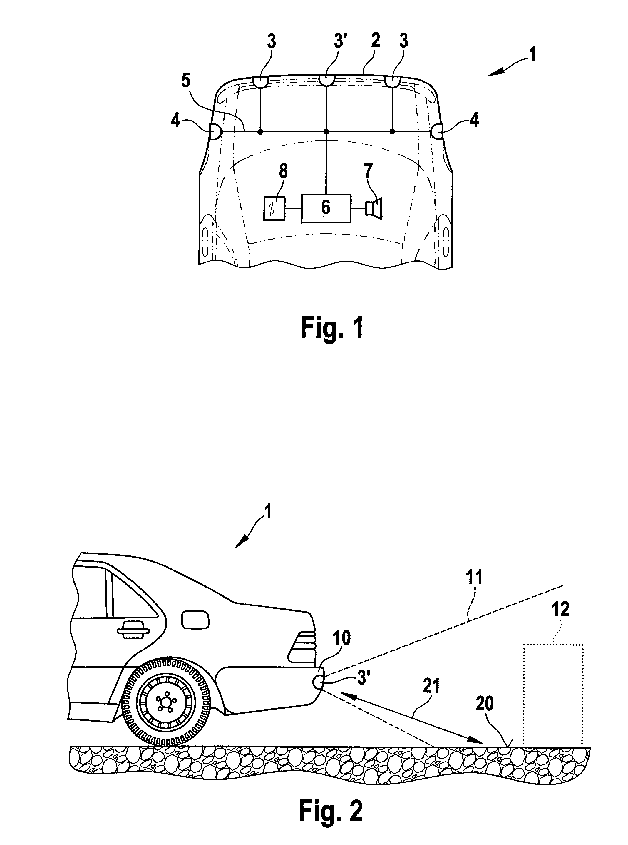
[0015]FIG. 1 shows a rear end of a vehicle 1. On a rear edge 2 of the vehicle there are situated ultrasonic sensors 3, 3′. It is also possible to situate the sensors at a front side of a vehicle. In a preferred specific embodiment, ultrasonic sensors 4 can also be situated on the lateral corners of the vehicle. The ultrasonic sensors are connected to a control unit 6 for example via a bus system 5. Control unit 6 controls the emission of ultrasonic signals by ultrasonic sensors 3, 3′, 4. The ultrasonic sensors each have for example a piezoelement that electrically excites a membrane to emit ultrasonic waves. The ultrasonic waves are reflected by an obstacle that may be situated in the vicinity of the vehicle and are reflected back to the ultrasonic sensors. Control unit 6 can switch ultrasonic sensors 3, 3′, 4 into a receive mode. In receive mode, the reflected ultrasonic waves excite the membrane of the ultrasonic sensors to vibration. This vibration can be converted into electrica...


PUM


Abstract

A method for functionally testing an ultrasonic sensor on a motor vehicle in which, in a test operating mode, an ultrasonic signal is emitted whose magnitude is large enough that under conventional conditions this ultrasonic signal is reflected by a ground surface in front of the vehicle and is received again. In this way, it can easily be determined that the ultrasonic sensor is functioning properly.

Description

FIELD OF THE INVENTION[0001]The present invention relates to a method for functionally testing an ultrasonic sensor on a motor vehicle.BACKGROUND INFORMATION[0002]From German Patent Application No. DE 4338743, a method and a device are known for testing an ultrasonic sensor. For this purpose, a reflecting object is situated on the vehicle at a defined distance from the ultrasonic sensor, the magnitude of the amplitude reflected by this object being evaluated as a measure of the sensitivity of the ultrasonic sensor. From the propagation time of the ultrasonic signal to the stationary obstacle, it is also possible to determine the ambient temperature. A corresponding measurement is possible in those sensors in whose vicinity a corresponding obstacle is actually provided on the vehicle.[0003]In addition, it is known that in the ultrasonic distance measurements the emitted signals are reflected not only by obstacles in the vicinity of the vehicle; a signal may also be reflected by the g...

Claims


Application Information

Patent Timeline
Patent Type & Authority Patents(United States)
IPC IPC(8): H04B17/00G01S3/80G01S15/931
CPCG01S7/52004G01S15/931G01S15/876G01S2007/52012G01S2015/938G01S2007/52009
Inventor PREISSLER, PETER
Owner ROBERT BOSCH GMBH
Learn More