Miniaturized dual-balanced mixer circuit based on a multilayer double spiral layout architecture

a layout architecture and mixer technology, applied in the field of miniaturized dual-balanced mixer circuits, can solve the problems of unsuitable use in the fabrication of miniaturized ic chips, and achieve the effect of reducing layout spa

Active Publication Date: 2011-11-22
NAT TAIWAN UNIV
View PDF4 Cites 7 Cited by
  • Summary
  • Abstract
  • Description
  • Claims
  • Application Information

AI Technical Summary

Benefits of technology

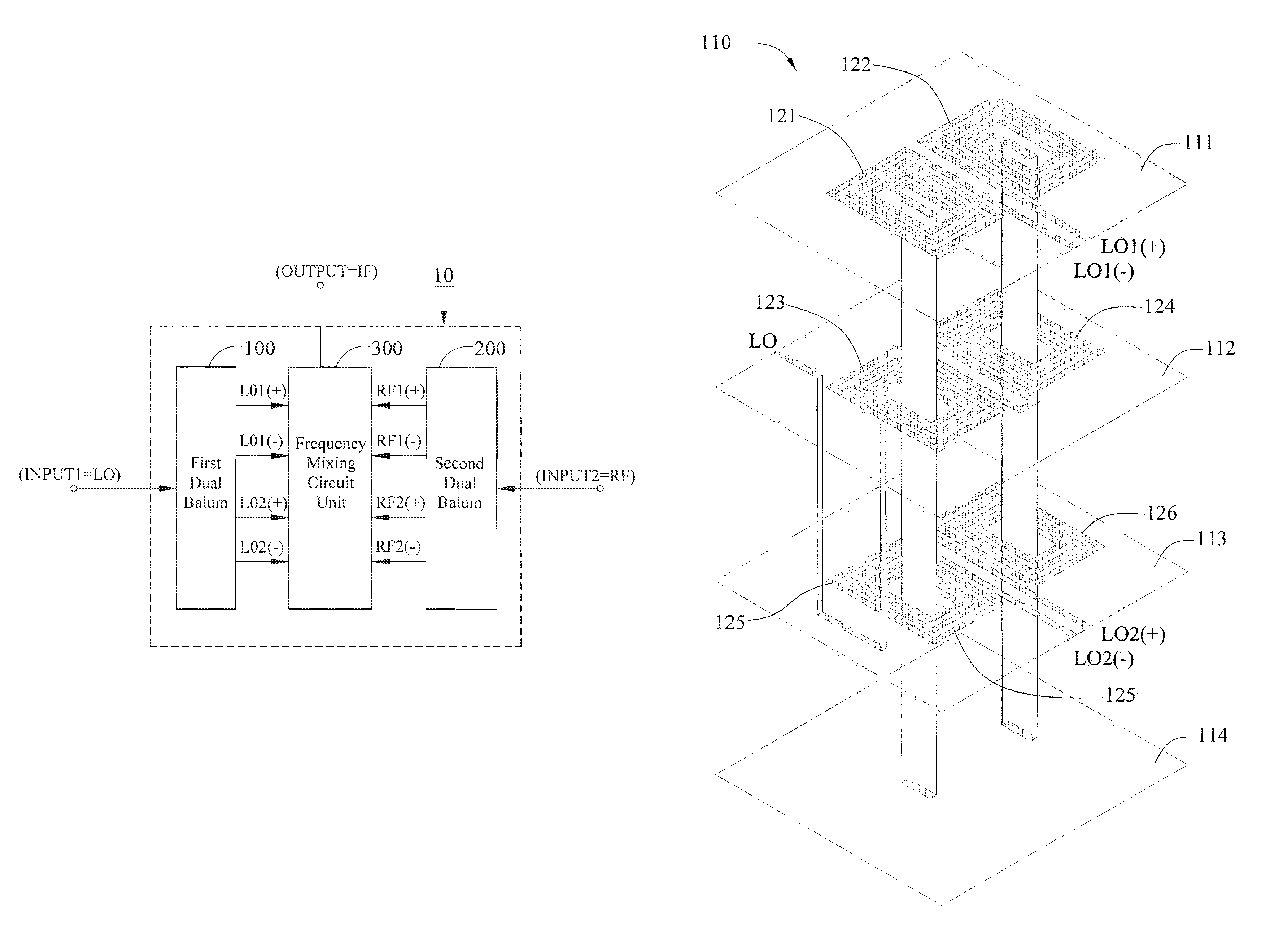
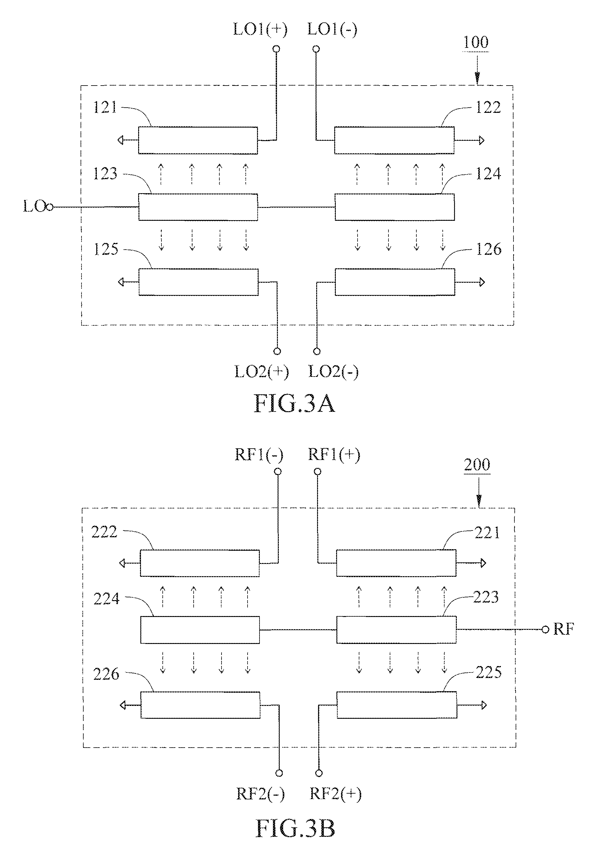
[0010]Compared to the conventional star-type DBM, the miniaturized dual-balanced mixer circuit of the invention is more advantageous to use in that the invention implemented in IC fabrication with a reduced layout space compared to the conventional star-type DBM owing to the use of a 3-dimensional double-spiral circuit layout architecture for the layout of the 2 balun circuit units. Specifically speaking, the invention only requires a layout area of about 15% of that of the conventional star-type DBM.

Problems solved by technology

In practical applications, however, one drawback of the conventional star-type DBM is that it is based on a dual-balun circuit architecture which is considerably large in size in IC implementation so that it is unsuitable for use in the fabrication of miniaturized IC chips.

Method used


Image

  • Miniaturized dual-balanced mixer circuit based on a multilayer double spiral layout architecture
  • Miniaturized dual-balanced mixer circuit based on a multilayer double spiral layout architecture
  • Miniaturized dual-balanced mixer circuit based on a multilayer double spiral layout architecture

Examples


first embodiment

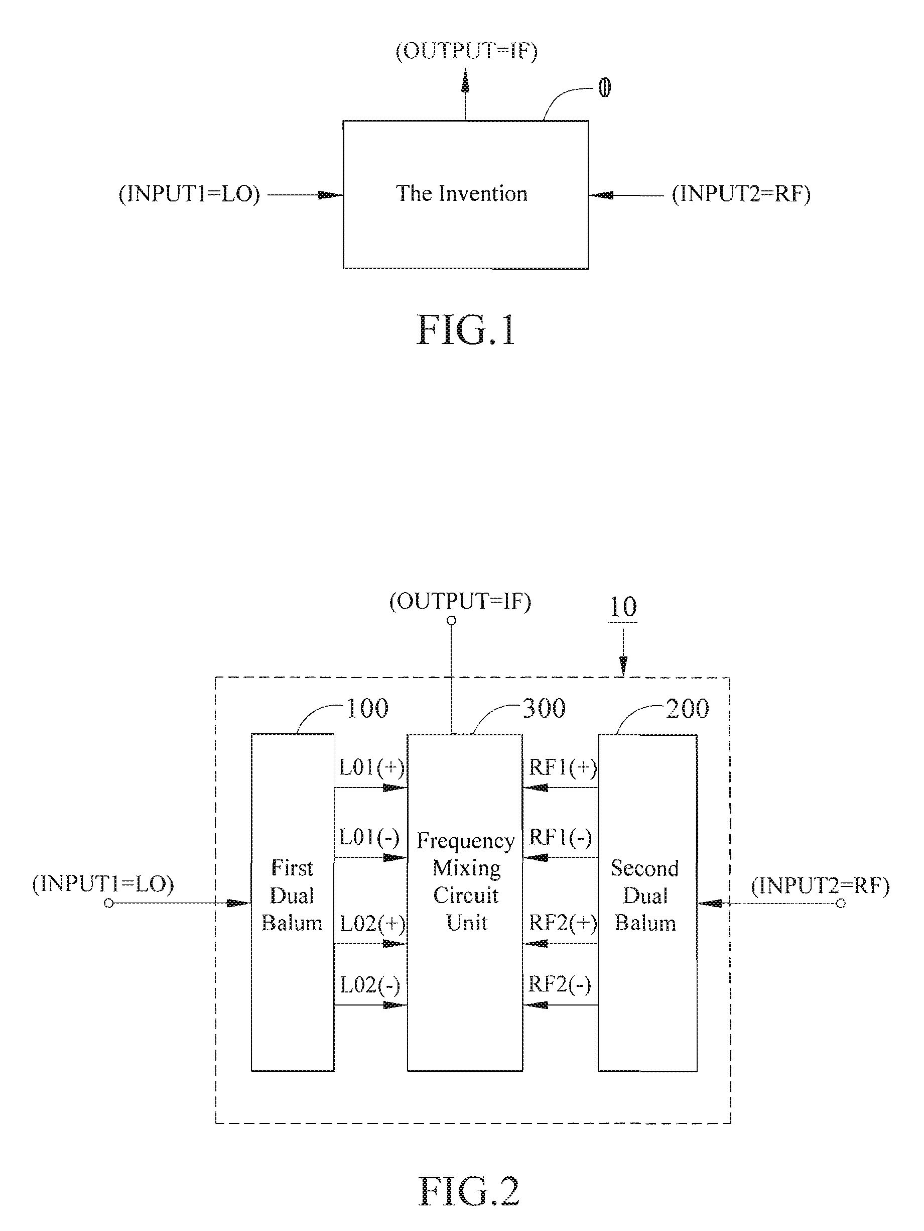
[0038]As shown in FIG. 4A, the frequency-mixing circuit unit 300 is based on a diode-switched circuit architecture which is composed of 4 diodes arranged in a particular manner that allows the generation of the intermediate-frequency signal IF in response to [LO1(+), LO1(−), LO2(+), LO2(−)] and [RF1(+), RF1(−), RF2(+), RF2(−)]. This diode-switched circuit architecture is based on a conventional circuit arrangement used in conventional star-type DBM circuitry, so that detailed description thereof will not be given in this specification.

(C2) Transistor-Switched Circuit Architecture (Frequency-Mixing Circuit Unit 300)

second embodiment

[0039]As shown in FIG. 4B, the frequency-mixing circuit unit 300 is based on a transistor-switched circuit architecture which is composed of 4 transistor-based circuit modules (each including a transistor, a resistor, and a capacitor) that are arranged in a particular manner to allow the generation of the intermediate-frequency signal IF in response to [LO1(+), LO1(−), LO2(+), LO2(−)] and [RF1(+), RF1(−), RF2(+), RF2(−)]. This transistor-switched circuit architecture is also based on a conventional circuit arrangement used in conventional star-type DBM circuitry, so that detailed description thereof will not be given in this specification.

Operating Characteristics of the Invention

[0040]FIG. 8A is a graph showing the insertion loss versus RF characteristics of each of the first balun circuit unit 100 and the second balun circuit unit 200 resulted from both circuit simulation and actual testing. It can be seen from this graph that in the frequency range from 25 GHz to 45 GHz, each of ...


PUM


Abstract

A miniaturized dual-balanced mixer circuit based on a multilayer double spiral layout architecture is proposed, which is designed for use to provide a frequency mixing function for millimeter wave (MMW) signals, and which features a downsized circuit layout architecture that allows IC implementation to be more miniaturized than the conventional star-type dual-balanced mixer (DBM). The proposed miniaturized dual-balanced mixer circuit is distinguished from the conventional star-type DBM particularly in the use of a 3-dimensional double-spiral circuit layout architecture for the layout of two balun circuit units. This feature allows the required layout area to be only about 15% of that of the conventional star-type DBM.

Description

BACKGROUND OF THE INVENTION[0001]1. Field of the Invention[0002]This invention relates to a miniaturized dual-balanced mixer circuit which is fully equivalent in function to a conventional star-type dual-balanced mixer (DBM) for frequency mixing of millimeter wave (MMW) signals, except that the construction of the invention is based on a multilayer double spiral layout architecture that allows its IC implementation to be more miniaturized than the conventional star-type DBM.[0003]2. Description of Related Art[0004]In communications systems, the mixer is an essential circuit component which receives an input of a carrier signal RF and mixes it with a local oscillation signal LO to thereby produce an intermediate-frequency signal IF, where IF is either an up-converted frequency or a down-converted frequency, i.e., IF=RF+LO or IF=RF−LO.[0005]In millimeter wave (MMW) communications systems, the dual-balanced mixer (DBM) is a widely utilized frequency mixing circuit. Various types of DBM...

Claims


Application Information

Patent Timeline
Patent Type & Authority Patents(United States)
IPC IPC(8): H04B1/26
CPCH03D9/0633H03D9/0675
Inventor KUO, CHE-CHUNGWANG, HUEI
Owner NAT TAIWAN UNIV
Why Eureka
Try Eureka