
Method and cascading differential signal circuit for receiving differential signals of data-bus, driving circuit of liquid crystal display and driving IC

Active Publication Date: 2006-10-31
HANNSTAR DISPLAY CORPORATION
View PDF3 Cites 3 Cited by
  • Summary
  • Abstract
  • Description
  • Claims
  • Application Information

AI Technical Summary

Benefits of technology

[0009]The object of the present invention is thus to provide a differential signal circuit having driving ICs connected in serial. Thus, the layout space is decreased. In addition, the cost is substantially decreased because the layers of the IC board are not necessary increased. Moreover, the electromagnetic interference decreases.

Problems solved by technology

Moreover, the electromagnetic interference decreases.

Method used


Image

  • Method and cascading differential signal circuit for receiving differential signals of data-bus, driving circuit of liquid crystal display and driving IC
  • Method and cascading differential signal circuit for receiving differential signals of data-bus, driving circuit of liquid crystal display and driving IC
  • Method and cascading differential signal circuit for receiving differential signals of data-bus, driving circuit of liquid crystal display and driving IC

Examples


Embodiment Construction

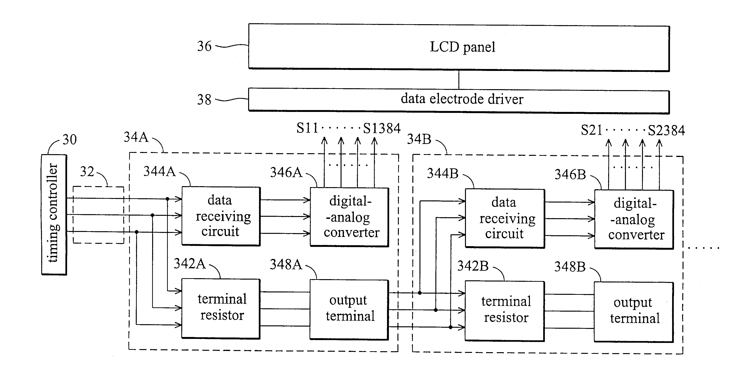
[0017]The cascading differential signal circuit according to the present invention is used for LCD. FIG. 3 shows the data-bus according to the embodiment of the present invention, which transmits differential type signals. The timing controller 30 outputs differential signals to the driving IC 34A through data-bus 32. Here, the differential signals are the signals of Reduced Swing Differential Signaling (RSDS) or mini-low voltage differential signaling (mini-LVDS).

[0018]The driving IC 34A comprises terminal resistor 342A connected to the timing controller 30 and acquiring an impedance match with the data-bus 32. Thus, the differential signal is transmitted when the terminal resistor 342A and data-bus 32 acquire an impedance match. The data receiving circuit 344A is coupled between the data-bus 32 and the terminal resistor 342A. The data receiving circuit 344A receives the differential signal and transforms it to digital signal. The transformed digital signal is input to the digital-...


PUM


Abstract

A cascading differential signal circuit. The processor outputs a differential signal. The data-bus transmits the differential signal. Each driving IC comprises a data receiving circuit, a terminal resistor, an output terminal and an analog-digital converter. The data receiving circuit is coupled to the data-bus for receiving the differential signals and encoding a digital signal. The terminal resistor is coupled to the data receiving circuit for acquiring an impedance match with the data-bus to transmit the differential signals. The output terminal is coupled to the terminal resistor for outputting the differential signals. The analog-digital converter is coupled to the data receiving circuit for converting the digital signal to an analog signal.

Description

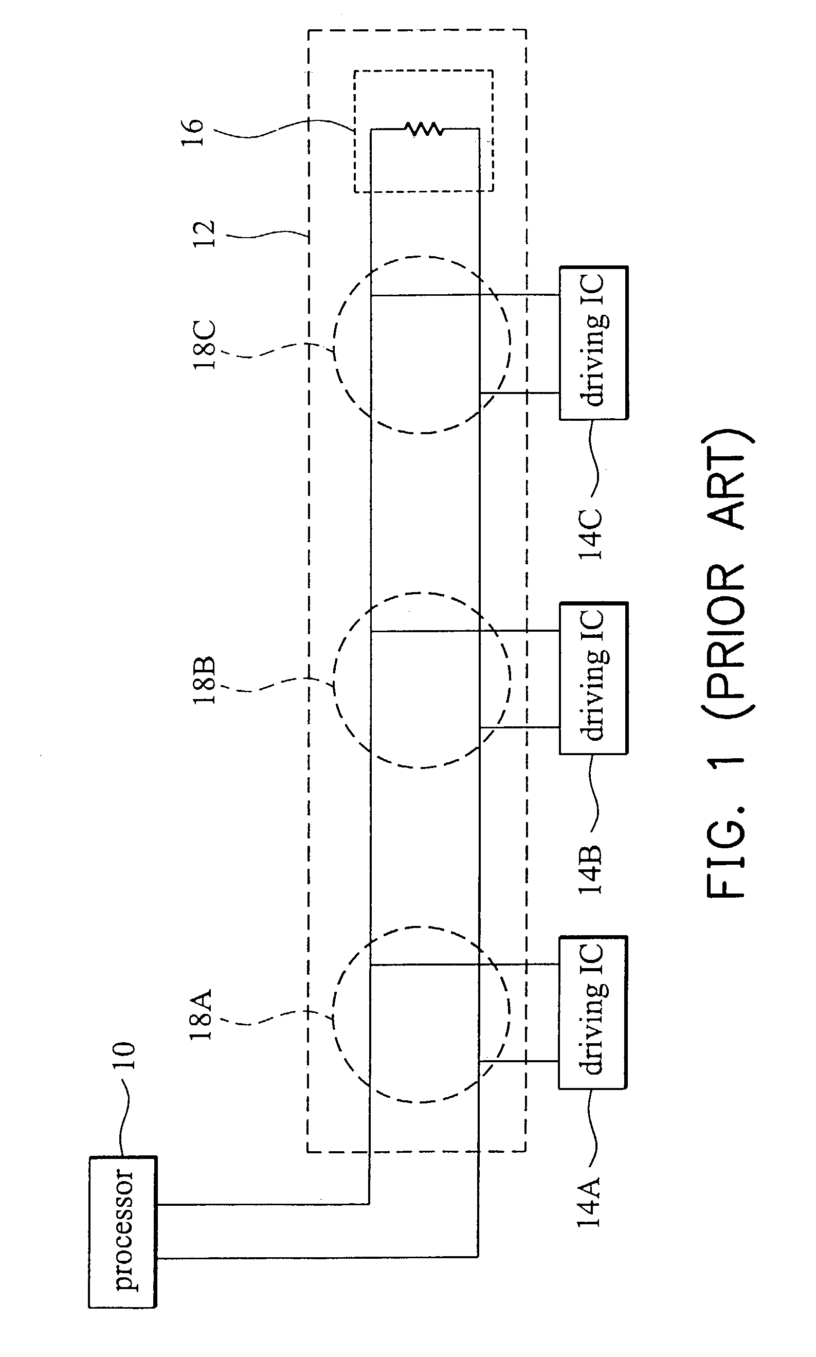
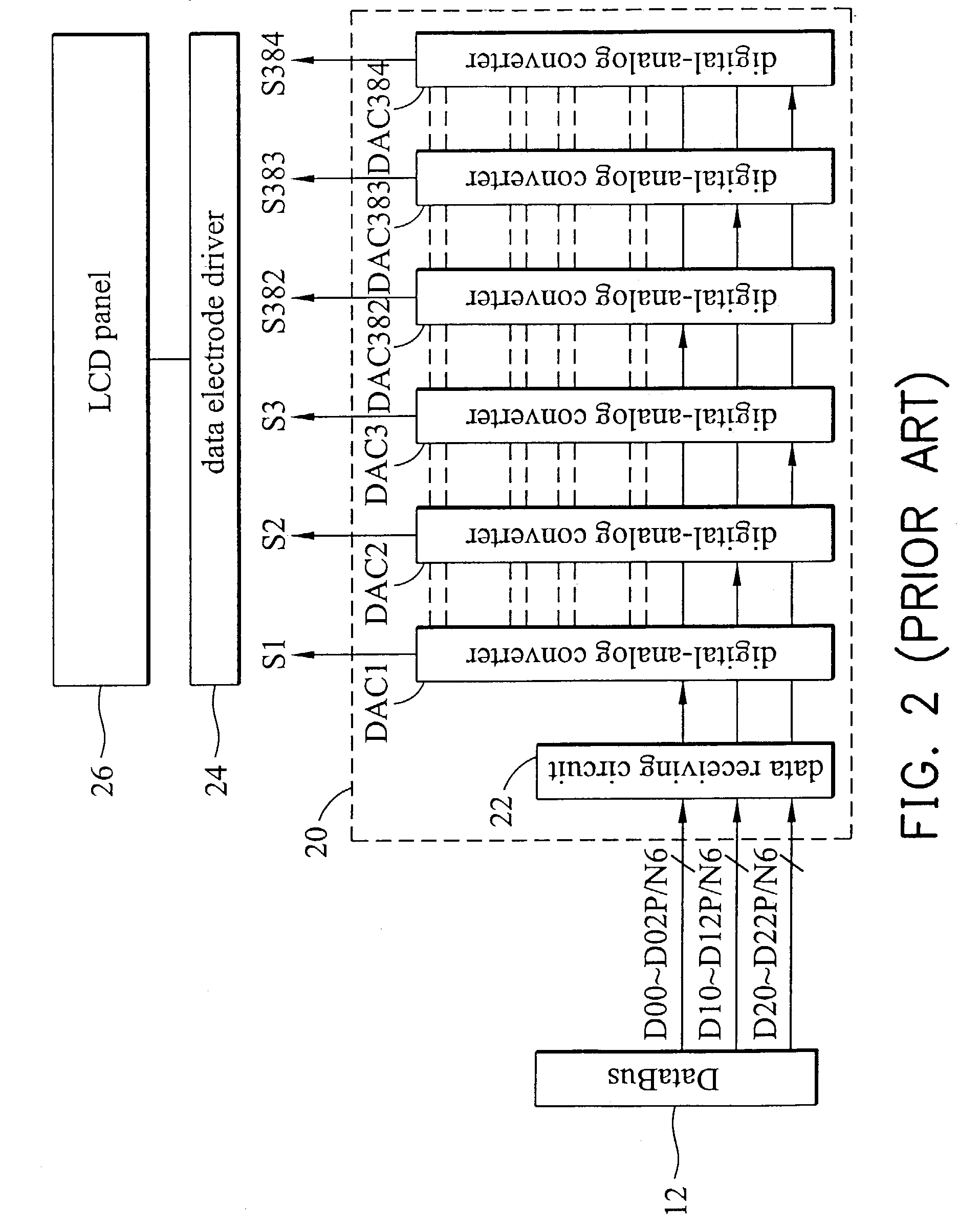
BACKGROUND OF THE INVENTION[0001]1. Field of the Invention[0002]The present invention relates in general to a driving integrated-circuit (IC). In particular, the present invention relates to a differential signal circuit and a driving circuit of a liquid crystal display (LCD) comprising driving ICs connected in serial.[0003]2. Description of the Related Art[0004]FIG. 1 shows the conventional data-bus transmitting signal by differential-type signal. The processor 10 outputs differential signals to the driving ICs 14A˜14C through data-bus 12. Here, the differential signals are transmitted when the input impedance and the output impedance of both sides of the data-bus match. Thus, terminal resistor 16 is utilized for obtaining impedance matching between the data-bus 12 and the processor 10.[0005]Each driving IC is respectively connected to the data-bus 12 in parallel to receive the differential signals output from the data-bus 12. The processor 10 is the timing controller when used in ...

Claims


Application Information

Patent Timeline
IPC IPC(8): G09G3/36G06F3/14
CPCG06F3/1446G09G3/3685G09G2310/0221G09G2310/027G09G2370/08
Inventor PAI, FENG-TING
Owner HANNSTAR DISPLAY CORPORATION
Learn More