
Snow removing machine

a technology of removing machines and snow, which is applied in the field of snow removal machines, can solve the problems of affecting the enhancement of the operability of the machine, the human operator, etc., and achieve the effect of reducing the load on the human operator and enhancing the operability

Active Publication Date: 2011-11-29
HONDA MOTOR CO LTD
View PDF6 Cites 0 Cited by
  • Summary
  • Abstract
  • Description
  • Claims
  • Application Information

AI Technical Summary

Benefits of technology

The present invention provides an improved snow removing machine that can alleviate a load on a human operator and achieve enhanced operability. The machine comprises an auger for removing accumulated snow and an accumulated snow height detection section for detecting the height of accumulated snow in front of the auger. The machine can automatically adjust the height of the auger based on the detected accumulated snow height, which eliminates the need for a human operator to set the target height position in advance. The machine can also lift the auger when the accumulated snow height is higher than the auger, allowing it to efficiently remove the snow. When no accumulated snow height is detected, the machine can lower the auger to save energy. The present invention allows the auger to move along the surface of the accumulated snow and perform snow removing along the surface, further enhancing the operability of the snow removing machine.

Problems solved by technology

However, with the snow removing machine disclosed in the 2004-278052 publication, there is a need for the human operator to set in advance a target height position of the auger, which would become a load on the human operator and thus impede enhancement of the operability of the machine.

Method used


Image

  • Snow removing machine
  • Snow removing machine
  • Snow removing machine

Examples


first embodiment

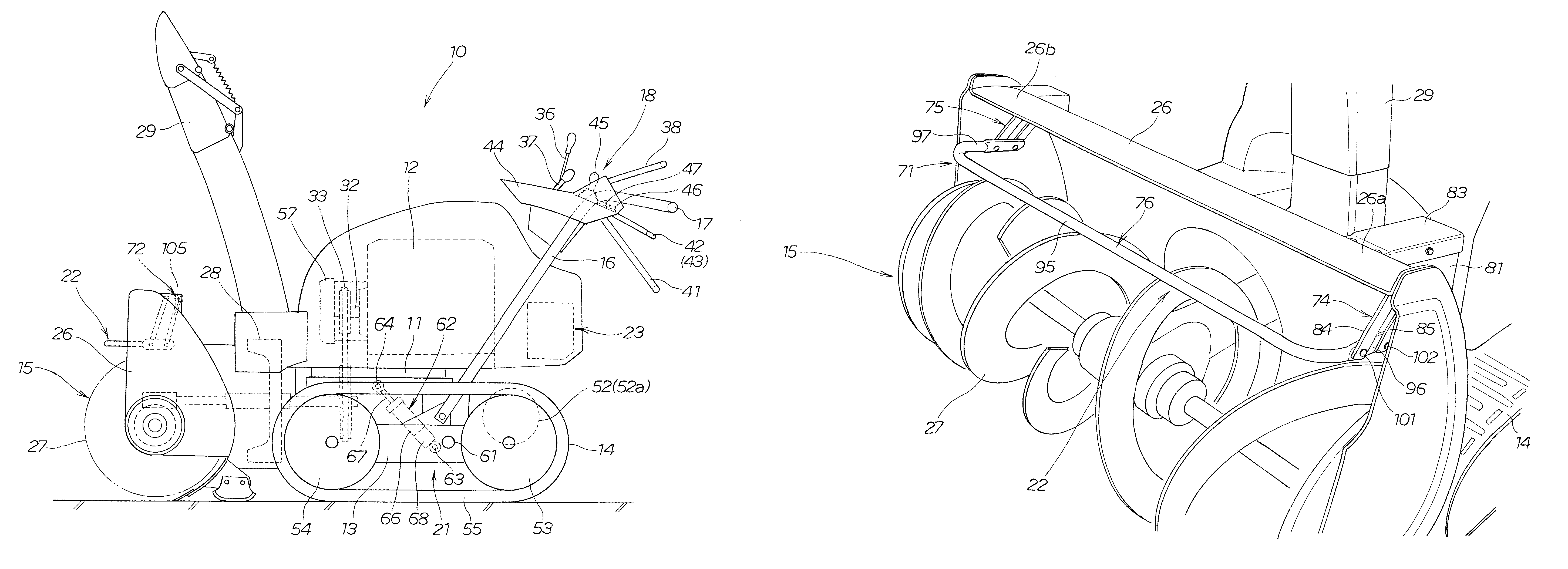
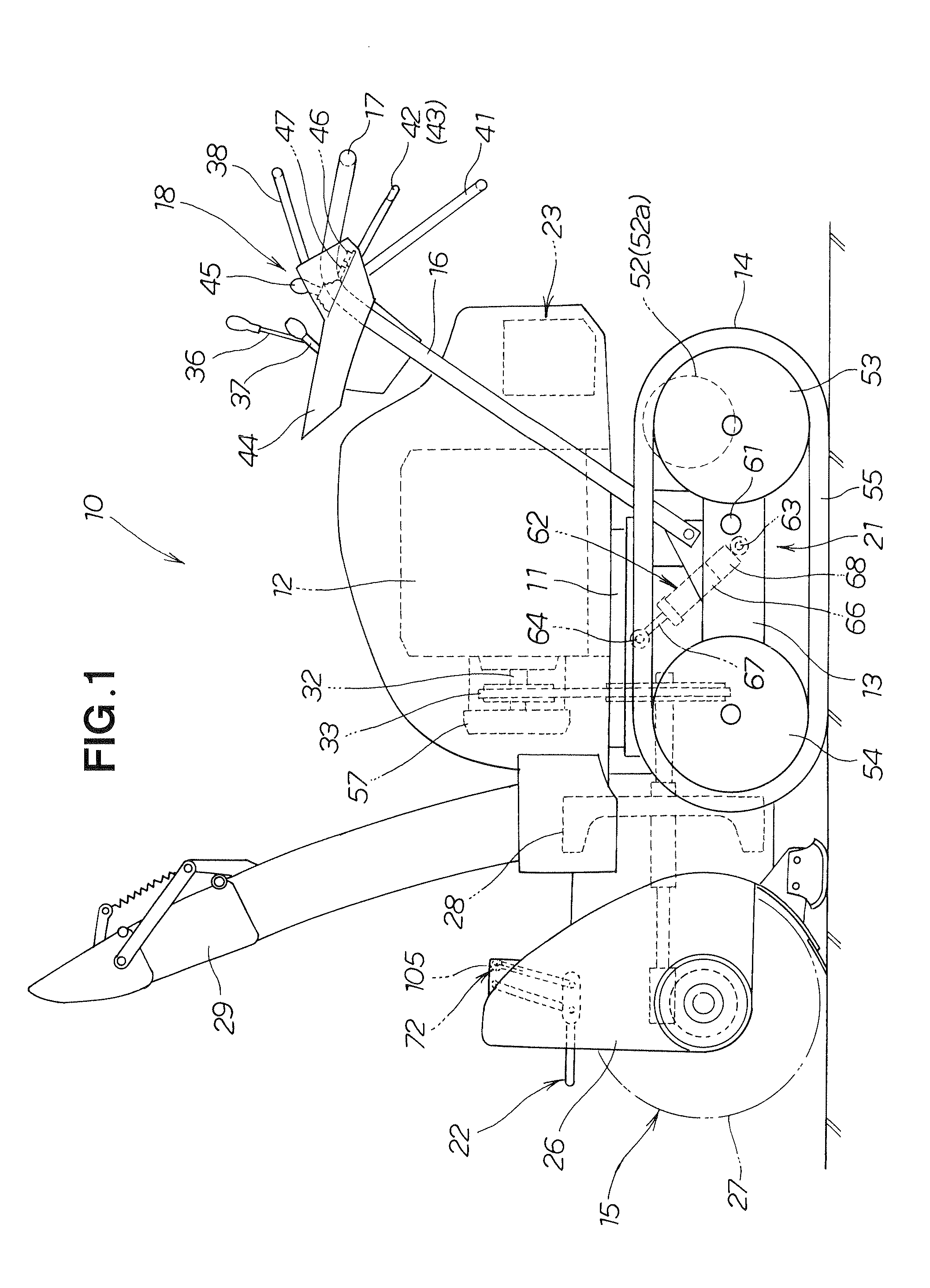
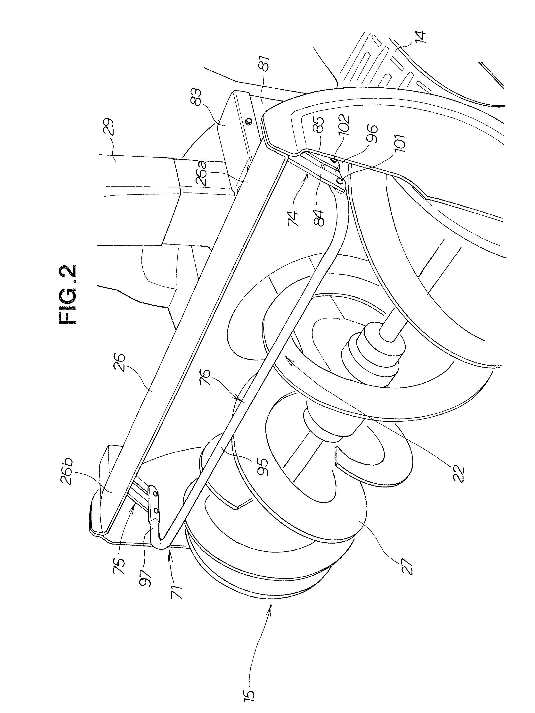
[0031]FIG. 1 is a view showing a first embodiment of the snow removing machine 10 of the present invention. As shown, the first embodiment of the snow removing machine 10 includes: an engine 12 mounted on an upper portion of a machine frame 11; left and right crawler-type traveling sections (hereinafter referred to as “crawler traveling sections”) 14 (only the left crawler traveling section 14 is shown in the figure) mounted to a lower portion of the machine frame 11 via a traveling section frame 13; a snow removing working section 15 mounted to a front portion of the machine frame 11; left and right handles 16 (only the left handle 16 is shown in the figure) mounted to a rear portion of the machine frame 11; grips (generally U-shaped grips) 17 fixed to upper end portions of corresponding ones of the left and right handles 16; and an operation section 18 provided in front of the grips 17.

[0032]The snow removing machine 10 further includes: an auger lifting and lowering section 21 fo...

second embodiment

[0096]Next, a description will be given about a second embodiment of the snow removing machine 10 which is characterized by provision of a control section 130 in place of the control section 23 provided in the first embodiment. The control section 130 has functions for detecting a “lifting / lowering or stopped state of the auger 27”, a “forward traveling or rearward traveling state of the snow removing machine 10”, a “rotating or stopped state of the auger 27” and an “accumulated-snow-height detected or accumulated-snow-height undetected state”.

[0097]Namely, the control section 130 determines whether the main switch button 46 is ON or OFF. Further, on the basis of “auger lifting / lowering information” output from the lifting and lowering lever detecting sensor operatively connected to the auger lifting and lowering lever 45, the control section 130 determines whether the auger 27 is currently being lifted or lowered through operation by the human operator or not currently being lifted...


PUM


Abstract

Snow removing machine includes an auger for removing accumulated snow, an accumulated snow height detection section for detecting a height of accumulated snow in front of the auger, an auger lifting and lowering section for lifting and lowering the auger, and a control section for controlling the auger lifting and lowering section to lift the auger in response to detection, by the accumulated snow height detection section, of the accumulated snow. By the provision of the accumulated snow height detection section, the present invention can save a human operator a trouble of setting in advance a target height position of the auger and thereby alleviate a load on the human operator.

Description

CROSS REFERENCE TO RELATED APPLICATION[0001]This application claims the priority of Japanese Application No. P2009-019633, filed Jan. 30, 2009, the entire specification, claims and drawings of which are incorporated herewith by reference.FIELD OF THE INVENTION[0002]The present invention relates to snow removing machines which include an auger for removing accumulated snow and an auger lifting and lowering section for moving the auger in an up-down direction.BACKGROUND OF THE INVENTION[0003]Among various conventionally-known types of snow removing machines is one which includes a snow removing working section (auger) capable of being lifted (moved upward) and lowered (moved downward). In snow removing machines of such a type, left and right crawler-type traveling sections (hereinafter referred to as “crawler traveling sections”) are provided on a traveling section frame, a machine frame is vertically pivotably mounted on the traveling section frame via a support pin, the machine fram...

Claims


Application Information

Patent Timeline
Patent Type & Authority Patents(United States)
IPC IPC(8): E01H5/09
CPCE01H5/04
Inventor YAMAZAKI, NOBUOMOROI, ATSUSHIKAWAKAMI, TOSHIAKI
Owner HONDA MOTOR CO LTD
Learn More