
Method for controlling shifts in an automated step-down transmission

a technology of automatic step-down transmission and shift control, which is applied in the direction of mechanical equipment, dynamo-electric gear control, transportation and packaging, etc., to achieve the effects of reducing the number of transmission lines

Active Publication Date: 2011-11-29
ZF FRIEDRICHSHAFEN AG
View PDF26 Cites 10 Cited by
  • Summary
  • Abstract
  • Description
  • Claims
  • Application Information

AI Technical Summary

Benefits of technology

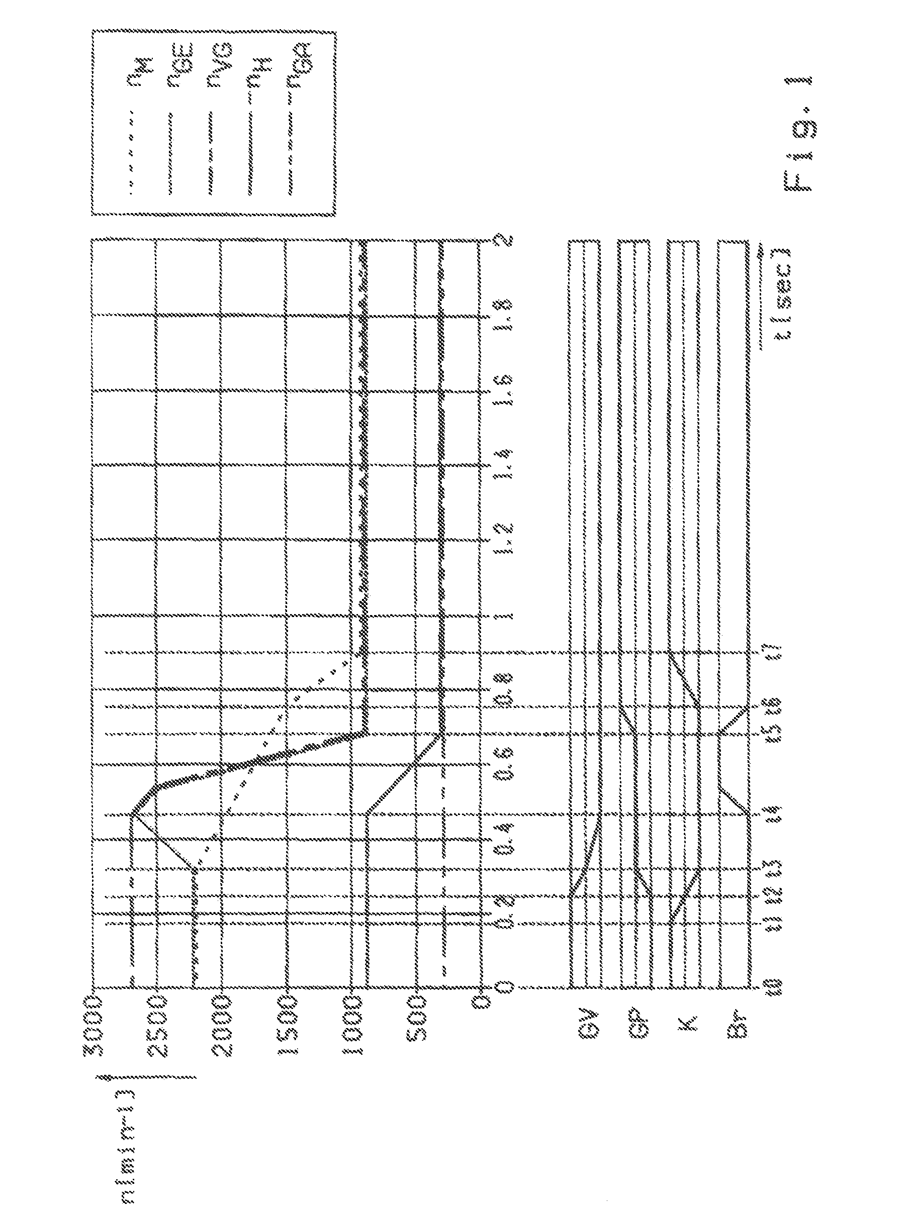
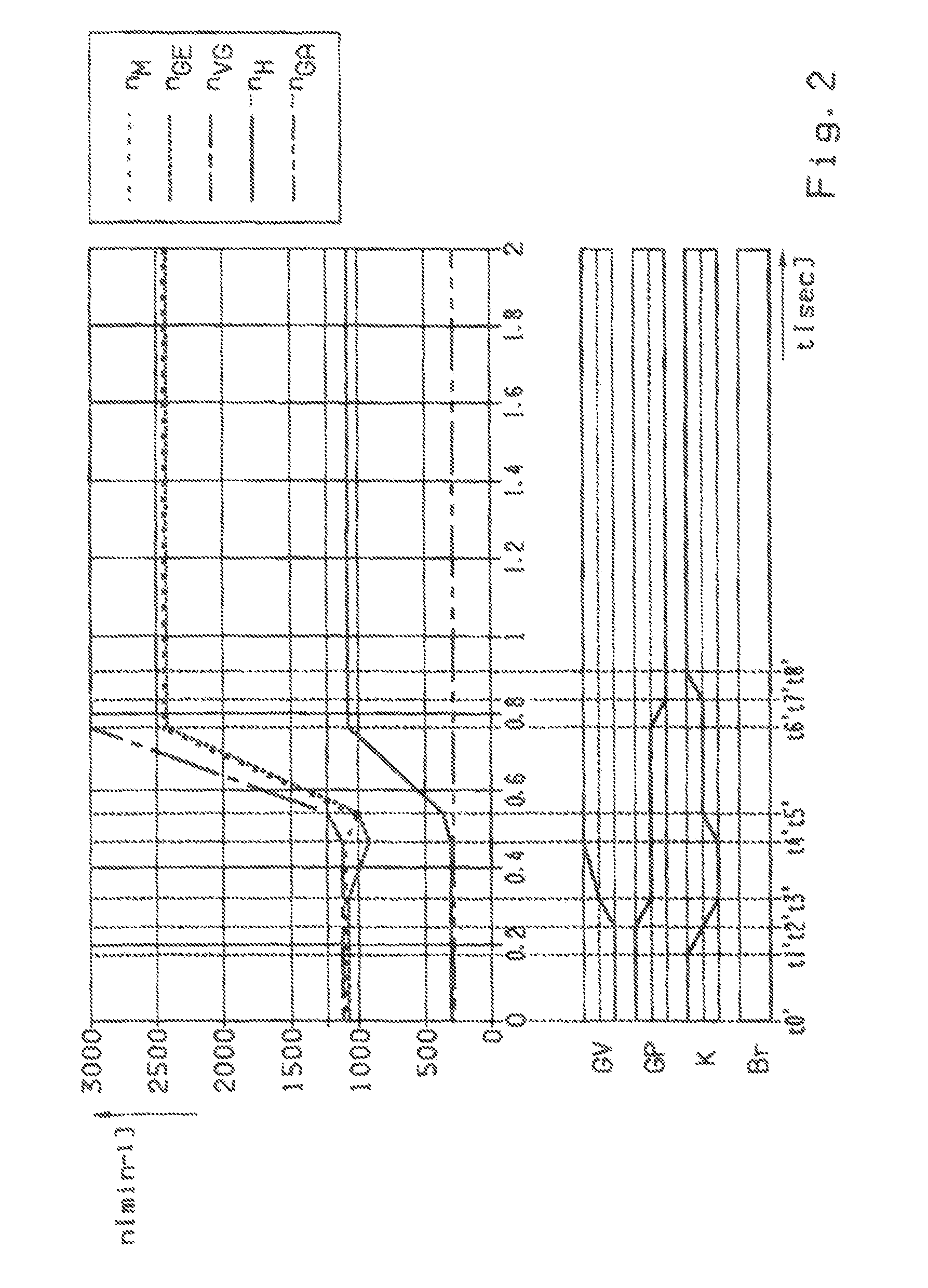
The present invention provides a method for controlling shifts in an automated step-down transmission of a vehicle that allows for range shifts with less wear and tear on the transmission. The method involves reducing the torque of the drive engine and disengaging the existing ratio step in the main transmission before engaging the target ratio step in the range group. The load reduction and disengagement steps are carried out in a specific order to ensure a smooth shift. The method can be used for both range upshifts and downshifts, and can also be used in the case of a splitter group. The use of the method results in a simplified and rapid shift process, and the components used in the transmission are used sparingly, leading to a longer useful life of the transmission.

Problems solved by technology

However, since many shifts in a step-down transmission require a change of gear ratio steps in a plurality of partial transmissions and thus take place with a relatively complex sequence, most known step-down transmissions are made to be shifted in a partially or fully automated manner.
When the range group GP downstream from the main transmission HG is shifted, then if the reverse ratio step R is engaged the associated shift clutches are affected by the additional problem that by virtue of the configuration concerned the interlock synchronizations involved usually only function when the input shaft (output shaft of the main transmission) is rotating in the forward direction and are not effective, or only to a limited extent, when the input shaft is rotating backward.

Method used


Image

  • Method for controlling shifts in an automated step-down transmission
  • Method for controlling shifts in an automated step-down transmission
  • Method for controlling shifts in an automated step-down transmission

Examples


Embodiment Construction

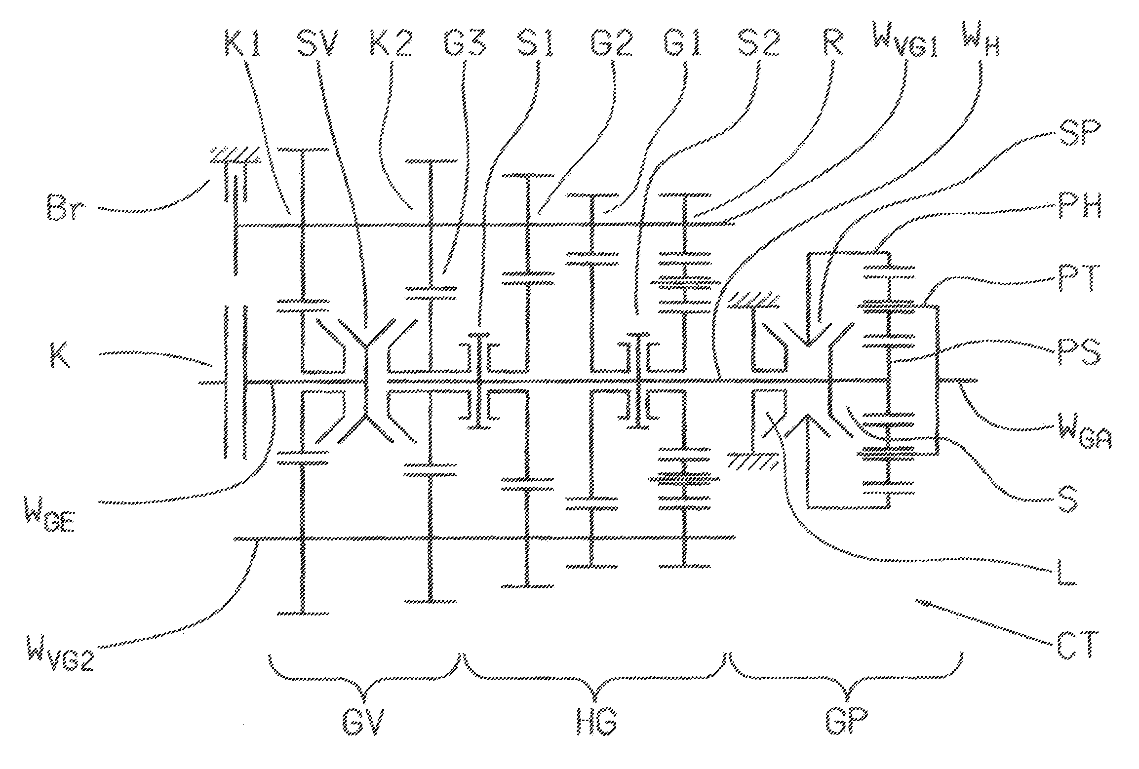
[0047]FIG. 3 shows an example of a step-down transmission CT with which the method according to the invention can be used. The step-down transmission CT comprises a main transmission HG, a splitter group GV upstream from and in drive connection with it, and a range group GP downstream from the main transmission HG, and in its configuration, relates to the design of a step-down transmission of the AS-Tronic series known per se.

[0048]The main transmission HG is made as a direct gear transmission of an intermediate transmission configuration and comprises a main shaft WH and two countershafts WVG1, WVG2, the first countershaft WVG1 being provided with a controllable transmission brake Br. The main transmission HG is made as a three-step transmission with transmission ratio steps G1, G2 and G3 for forward driving and one ratio step R for reversing. The loose gearwheels for the ratio steps G1, G2 and R are each mounted to rotate on the main shaft WH and can be engaged by associated claw ...


PUM


Abstract

A method of controlling an automated step-down transmission, arranged in a drivetrain between an engine and a drive axle, which includes a multi-stage main transmission and a range group. The main transmission has an intermediate transmission style with a countershaft having a transmission brake and an input shaft connected, via a clutch, to the engine. The main transmission shifts, without being synchronized, and the range group shifts, after synchronization, such that the engaged gear ratio of the main transmission remains engaged during a range shift operation. The range shift is accomplished by firstly reducing drive engine torque; secondly, disengaging the existing gear ratio of the range group; thirdly, remotely synchronizing the target gear ratio in the range group; fourthly, engaging the target gear ratio in the range group; and fifthly, increasing the drive engine torque.

Description

[0001]This application claims priority from German patent application serial no. 10 2008 000 752.8 filed Mar. 18, 2008, and also claims priority from German patent application serial no. 10 2008 042 345.9 filed Sep. 25, 2008.FIELD OF THE INVENTION[0002]The invention concerns a method for controlling shifts in an automated step-down transmission arranged in a drivetrain of a motor vehicle between a drive engine and a drive axle and comprises at least a multi-stage main transmission and, downstream therefrom, a range group, and in which the main transmission has an intermediate transmission structure with at least one countershaft provided with a controllable transmission brake, an input shaft being connected to the drive engine via a separate clutch, such that the main transmission can be shifted unsynchronized and the range group after synchronization, and such that the transmission ratio engaged in the main transmission before and after the range shift is identical.BACKGROUND OF TH...

Claims


Application Information

Patent Timeline
Patent Type & Authority Patents(United States)
IPC IPC(8): H02P17/00B60W30/18
CPCB60W10/06B60W30/19F16H61/0403F16H61/702F16H63/502F16H2061/0411Y10T477/6242F16H2306/48B60W10/111Y10T477/33Y10T477/24Y10T477/677Y10T477/62429F16H2306/42
Inventor STEINBORN, MARIOBREUER, JOCHEN
Owner ZF FRIEDRICHSHAFEN AG
Learn More