Range of motion device

a range of motion and joint technology, applied in the field of adjustable orthoses for stretching tissue, can solve the problems of joint and surrounding tissue not being able to achieve a wide range of motion without risking damage to the joint or surrounding tissue, and the range of motion through which the body moves may chang

Active Publication Date: 2011-11-29
BONUTTI RES
View PDF304 Cites 6 Cited by
  • Summary
  • Abstract
  • Description
  • Claims
  • Application Information

AI Technical Summary

Benefits of technology

[0009]For example, a patient fitted with a joint treatment apparatus according to the present invention is expected to gradually increase range of motion in the joint over time. Initially, however, the joint and surrounding tissue may not be capable of a wide range of motion without risking damage to the joint or surrounding tissue. To account for this, a force absorber or cushioning device may be used to limit the amount of force exerted on a joint, or at least reduce it to a lower level than may have been exerted if the device did not utilize a force absorber or cushioning device. As the resistive forces in the joint and surrounding tissue reach a threshold amount, the force absorber or cushioning device may bend, deflect, compress, or otherwise absorb some of this energy. As flexibility in the joint and surrounding tissue increases, operation of the force absorber or cushioning device will decrease and the range of motion the joint travels through will increase.

Problems solved by technology

Thus, while the settings of the device may be established to recreate substantially the same underlying movement of some component parts, changes in the treated joint over time may mean that the range of motion through which it moves may change.
Initially, however, the joint and surrounding tissue may not be capable of a wide range of motion without risking damage to the joint or surrounding tissue.

Method used


Image

  • Range of motion device
  • Range of motion device
  • Range of motion device

Examples


Embodiment Construction

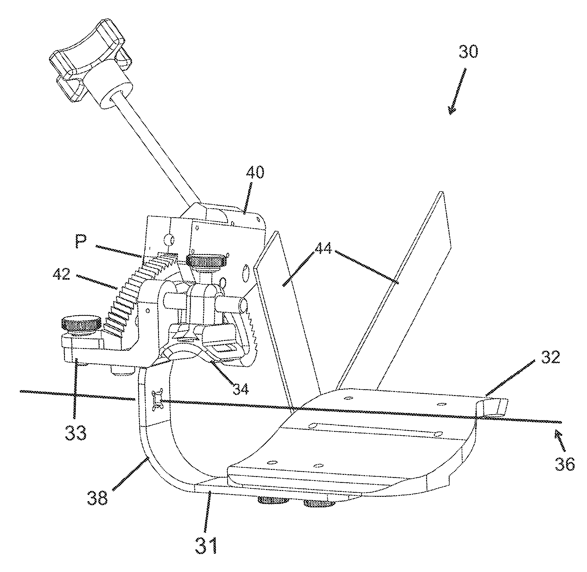
[0031]The present invention relates to an orthosis for causing a joint to flex or move through a range of motion. One exemplary application of an orthosis of the present invention is in treatment of a toe of a patient's foot. While the invention is believed to provide significant improvements in this area of treatment, it may likewise be of benefit in treating other joints, such as ankles, knees, hips, fingers, wrists, elbows, shoulders, or the spine.

[0032]Furthermore, while many examples provided herein may illustrate the invention used to treat the metatarsal and proximal phalanx of the toe, these examples are non-limiting on other joints of the toe that also may be treated by the present invention. It is understood by those skilled in the art that the other joints of the toe may be flexed or extended, without departing from the spirit and scope of the invention. Additionally, the present invention is described in use on the “big” toe or hallux on the foot. Thus, it should be unde...


PUM

PropertyMeasurementUnit
constant radius of curvatureaaaaaaaaaa
radius of curvatureaaaaaaaaaa
orthosis axis of rotationaaaaaaaaaa

Abstract

The present invention provides an orthosis for stretching tissue around a joint of a patient between first and second relatively pivotable body portions. The orthosis includes a first member affixable to the first body portion and including a first extension member extending therefrom. A second member affixable to the second body portion is also included and has a second extension member having an arcuate shape extending therefrom. The second extension member is operatively connected to the first extension member and travels through the first extension member along an arcuate path when the second arm member is moved from a first position to a second position relative to the first arm member.

Description

FIELD OF THE INVENTION[0001]The present invention relates to an adjustable orthosis for stretching tissue in the human body. In particular, the present invention relates to an adjustable orthosis which can be used for stretching tissue such as ligaments, tendons or muscles around a joint during flexion or extension of the joint.BACKGROUND OF THE INVENTION[0002]In a joint, the range of motion depends upon the anatomy and condition of that joint and on the particular genetics of each individual. Many joints primarily move either in flexion or extension, although some joints also are capable of rotational movement in varying degrees. Flexion is to bend the joint and extension is to straighten the joint; however, in the orthopedic convention some joints only flex. Some joints, such as the knee, may exhibit a slight internal or external rotation during flexion or extension.[0003]Most people do not appreciate the complexity of joint motion until something goes wrong, such as when an injur...

Claims


Application Information

Patent Timeline
Patent Type & Authority Patents(United States)
IPC IPC(8): A61F5/00
CPCA61H1/02Y10T29/49826A61H2001/0207A61H1/0266A61H2001/027A61H2201/14A61H2201/5007
Inventor BONUTTI, BORIS P.BONUTTI, PETER M.RUHOLL, KEVIN R.PHILLIPS, GLEN A.
Owner BONUTTI RES
Why Eureka
Try Eureka