Scrubber

a scrubber and scrubber technology, applied in the direction of reversed direction vortex, separation process, vortex flow apparatus, etc., can solve the problems of pressure loss, which is also an essential factor, and achieve the effect of good primary liquid separation, good liquid separation, and reduced liquid fraction

Active Publication Date: 2011-11-29
DEN NORSKE STATS OLJESELSKAP AS
View PDF27 Cites 1 Cited by
  • Summary
  • Abstract
  • Description
  • Claims
  • Application Information

AI Technical Summary

Benefits of technology

[0018]With the scrubber of the invention a good separation of liquid from gas is achieved by rotation / gravitation with minimum generation of turbulence and minimum entrainment of droplets. Further, the accumulation of upstream coalesced liquid is passed relatively unaffected of the gas flow down to the bottom section. The inlet and the fluid way according to the invention are robust with respect to variations in liquid fraction in the feed flow, and result in reduced liquid fraction in the feed to downstream located liquid separation equipment. The result is a good primary liquid separation, with 50 to 75% reduced liquid contents in the gas downstream of the fluid way compared to conventional inlets. The operation of optional devices in the top and bottom of the scrubber, to reduce the liquid ratio further, also becomes more effective.

Problems solved by technology

Pressure loss is also an essential problem with respect to separation of liquids and / or particles from a fluid flow that in substance comprises gas.

Method used


Image

  • Scrubber
  • Scrubber
  • Scrubber

Examples


Embodiment Construction

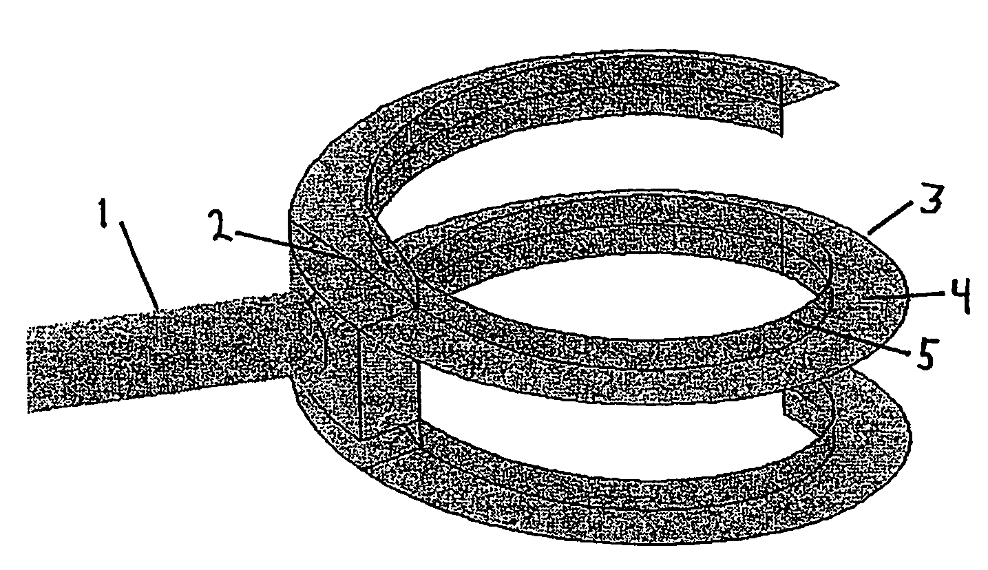
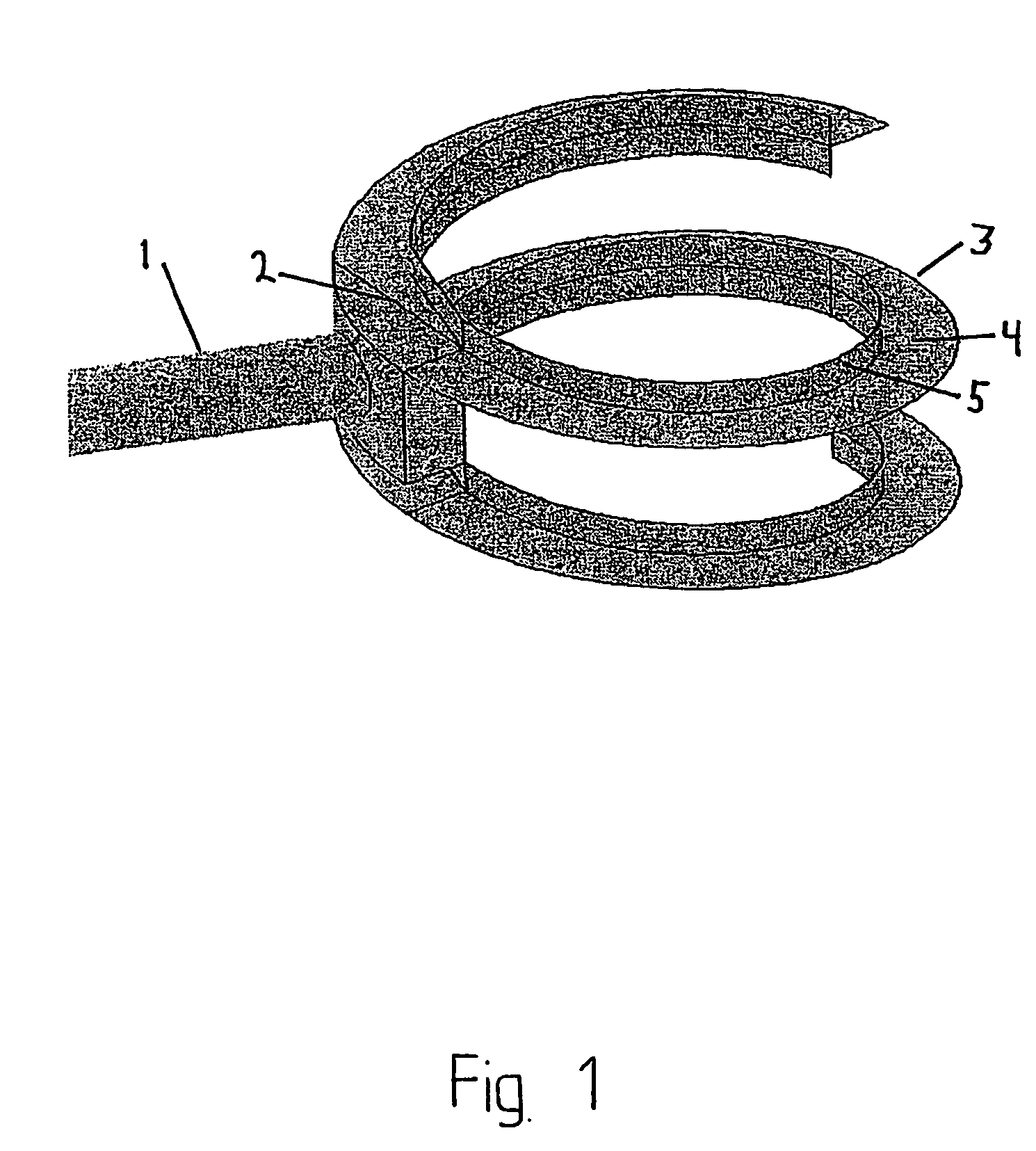
[0022]With reference to FIG. 1, a typical embodiment of the distinguishing features of the scrubber according to the present invention is illustrated, more specifically a fluid inlet and a fluid way. The inlet 1 directs the fluid flow towards a deflection plate 2 which again directs the fluid flow into a fluid way 3. The fluid way consists of a guiding plate 4 and an upwardly extending edge 5 fastened along the inner edge of the guiding plate towards the center of the scrubber.

[0023]The scrubber according to the invention preferably comprises a fluid way in the form of a guiding plate that is fastened on the inner wall of the scrubber in spiral form from a level above the inlet to a level just above the outlet for liquid. The guiding plate extends out towards the center axis of the scrubber a distance from 5% to 20% of the inner diameter of the scrubber and is equipped with an upwards extending edge of height 75-150% of the width of the guiding plate closest towards the center of th...


PUM

PropertyMeasurementUnit
inner diameteraaaaaaaaaa
distanceaaaaaaaaaa

Abstract

A scrubber for separation of liquid phase and any other constituents from a fluid now that in substance includes a gas. The scrubber is formed as a standing vessel with round cross section, with an outlet for liquid from the bottom and an outlet for gas from the top. The scrubber is distinguished in includes a fluid inlet that either is tangentially oriented relative to the inner wall of the scrubber or equipped with a deflection plate, such that introduced fluid is directed tangentially horizontal or with a small downward slope along the inner wall of the scrubber, into and through a fluid way arranged as a downwards directed spiral within the scrubber, along the inner wall, from a level over or at the inlet to a level at or close to the outlet for liquid, with an opening for gas escape inwards toward the center of the scrubber. The scrubber according to the invention results in very low liquid entrainment.

Description

BACKGROUND OF THE INVENTION[0001]1. Field of the Invention[0002]The present invention regards separation of liquid from gas. In particular, the present invention regards a scrubber with beneficial properties.[0003]2. Description of the Related Art[0004]A number of known installations function to separate fluids of different density by use of a cyclone principle. The principle works by the deflection of a compounded fluid flow for example along the inner wall of a vessel, whereby the heavier constituents move to the outside of the curved fluid flow and are accumulated towards the inner wall of the vessel, after which the heavier constituents as a result of gravitation can be directed to a reservoir or outlet in the bottom of the vessel. The lighter constituents will be concentrated in the center area of the vessel, after which they can be taken out through an outlet beginning in the center area of the vessel.[0005]Some examples of cyclones that can be used for separation of fluids of...

Claims


Application Information

Patent Timeline
Patent Type & Authority Patents(United States)
IPC IPC(8): B01D47/00B01D45/16B04C5/04B04C5/103
CPCB01D45/16B04C5/04B04C5/103
Inventor GJERTSEN, LARS HENRICKFREDHEIM, ARNE OLAVJENSSEN, CARL-BIRGERGJOEN, BARD
Owner DEN NORSKE STATS OLJESELSKAP AS
Why Eureka
Try Eureka