Supercharge Your Innovation With Domain-Expert AI Agents!

Multiple-shell silencer / rear shell port

a multi-shell, rear shell technology, applied in the direction of silencing apparatus, engine components, machines/engines, etc., can solve the problems of relatively hot front shell, relatively heavy known exhaust system, complicated and time-consuming assembly of the mentioned exhaust system, etc., to achieve the effect of reducing sound

Active Publication Date: 2011-12-06
DOLMAR
View PDF10 Cites 1 Cited by
  • Summary
  • Abstract
  • Description
  • Claims
  • Application Information

AI Technical Summary

Benefits of technology

[0005]It is thus the object of the present invention to provide an exhaust system for an internal combustion engine with a catalytic converter element which is of a simple and compact design requiring only few components. In addition, the centre of gravity of the exhaust system is to be arranged closely to the internal combustion engine or cylinder.
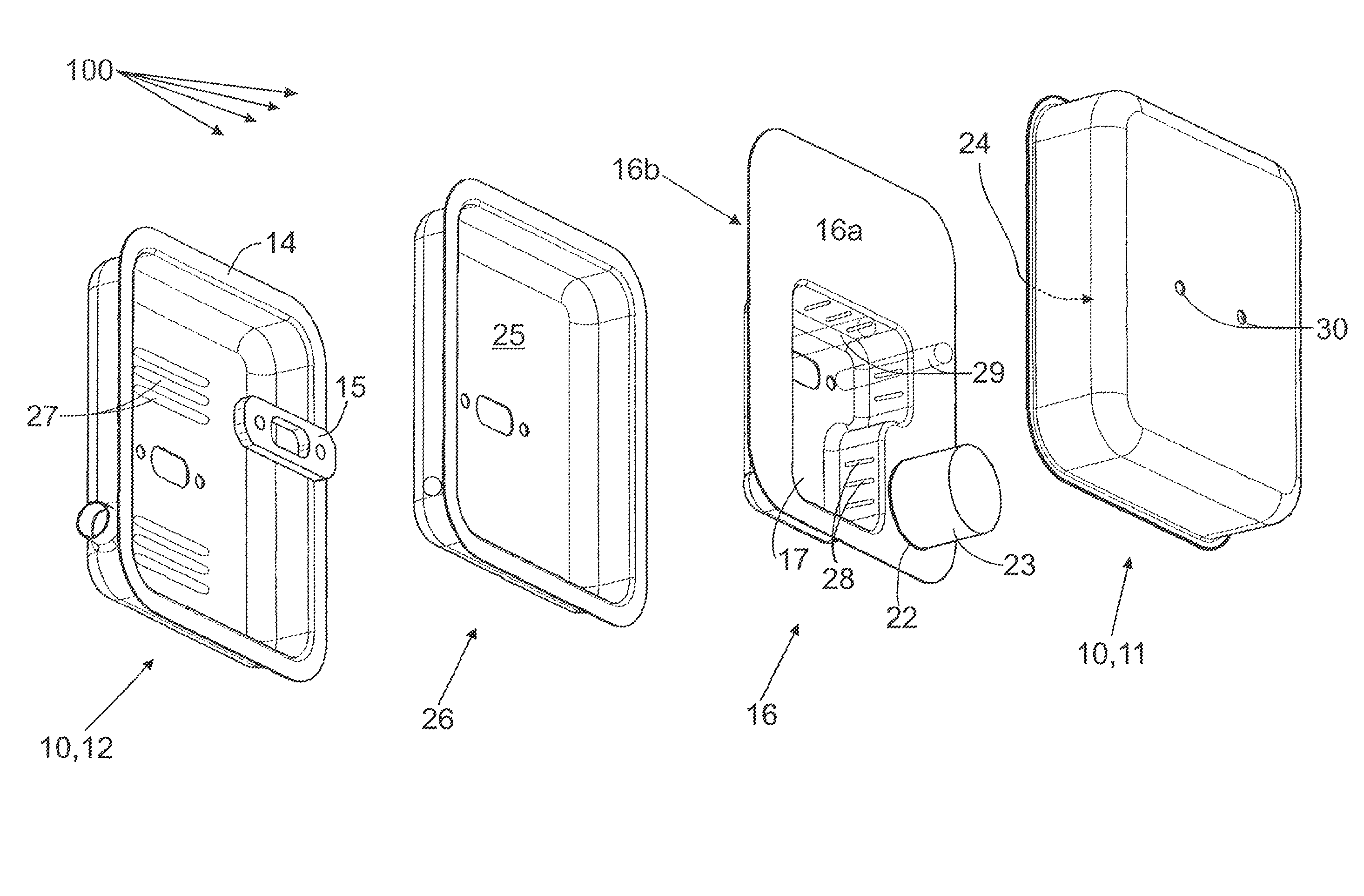
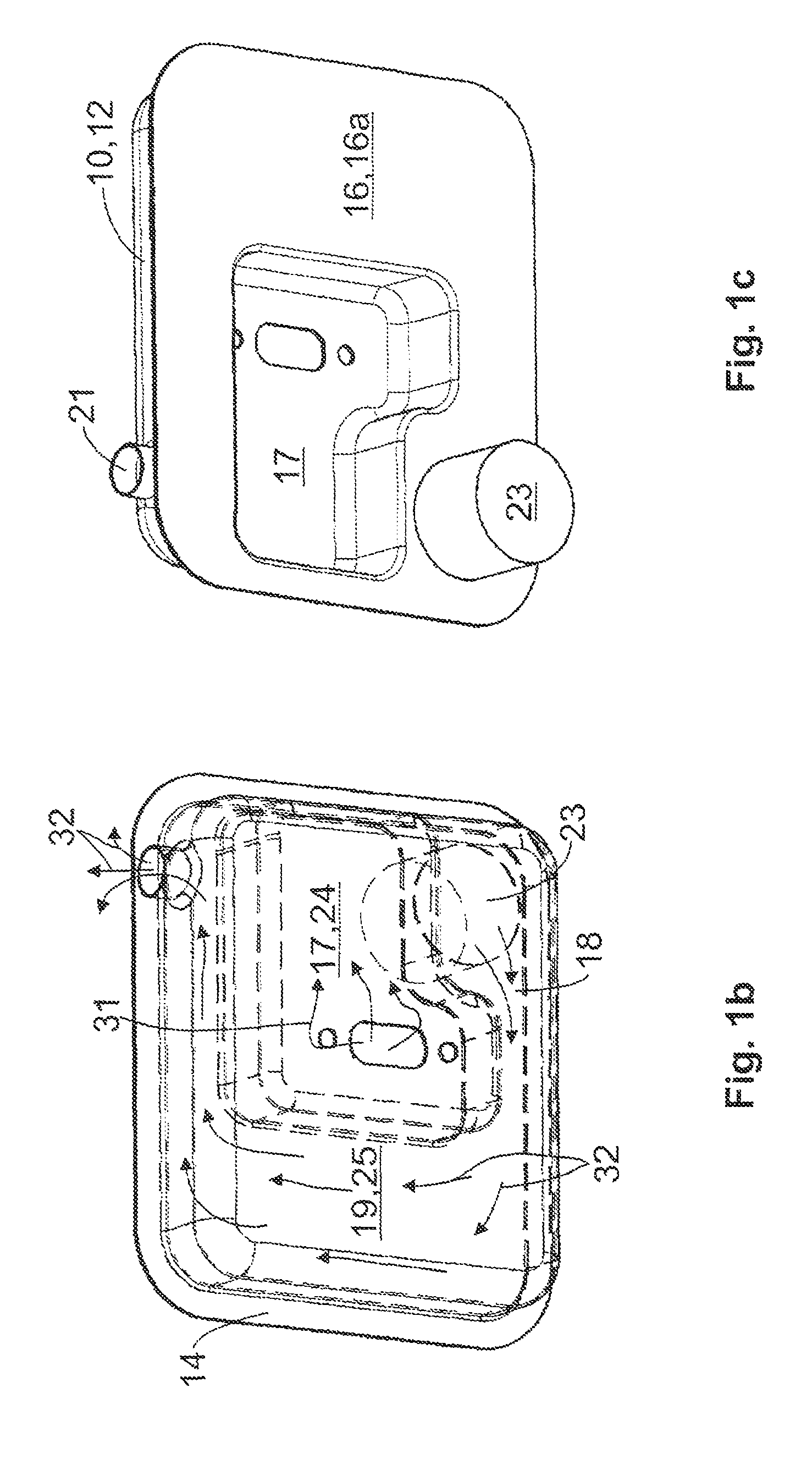
[0010]To cool the converted exhaust gas originating from the catalytic converter element in the exhaust port the exhaust port is guided more preferably O or U-shaped about the prechamber. Thus the prechamber simultaneously serves to cool the hot exhaust port. Through the skilful design of the prechamber, which for example can have the outer shape of a “P” the exhaust port can be laid. Here it is conceivable through additional projections and bulges in the prechamber which protrude into the exhaust port to improve the cooling of the exhaust port. In addition, the exhaust port can be curved and / or designed meander-shaped. Likewise, additional cooling surfaces can optionally protrude from the prechamber into the exhaust port in order to bring about an improved heat exchange between the prechamber and the exhaust port. Here it has to be mentioned once more that the front shell with the exhaust system according to the invention does not come in direct contact with the hot converted exhaust gas and thus is of a rather cool design. Conversely, the rear shell can come in direct contact with the hot converted exhaust gas from the catalytic converter element as a result of which additional heating can occur. This addition heat on the rear shell can be discharged through the engine cooling air. To this end suitable cooling surfaces or ribs can be designed on the rear shell.
[0012]By using the intermediate shell in the exhaust system according to the invention a sub-division of the interior space of the exhaust system in two gas-tight regions can be brought about. Here, the intermediate shell has only two through apertures, namely on the one hand for the entry of the untreated exhaust gas from the internal combustion engine and on the other hand an aperture in which preferably the catalytic converter element is arranged, through which the hot treated exhaust gases can reach. The first region has the prechamber and the second region the exhaust port. Since the catalytic converter element is arranged in the second aperture of the intermediate shell the entire exhaust gas has to pass the catalytic converter element to reach the exhaust port and thus the exhaust outlet aperture. In this way it can be ensured that complete catalytic treatment of the exhaust gas takes place.
[0015]With another version of the exhaust system according to the invention at least one perforated exhaust screen can be provided after the exhaust inlet aperture which more preferably can be arranged in the prechamber. This perforated exhaust screen serves to reduce sound. The perforated exhaust screen itself can be arranged in the prechamber on the intermediate plate. It is also conceivable to arrange the perforated exhaust screen on at least one spacer sleeve in a fixed location. This spacer sleeve itself can serve for leading a fastener through the exhaust system. To securely hold the exhaust system on the hand-held machine two fasteners can be provided which are attached in the region of the exhaust inlet aperture on the internal combustion engine. These fasteners can be guided into the engine through the spacer sleeves through which it is avoided that the fasteners deform the exhaust system upon tightening of the fasteners. These spacer sleeves can then also serve to fasten the perforated exhaust screen.

Problems solved by technology

In addition, the assembly of the mentioned exhaust system is complicated and time-consuming.
In addition, the known exhaust system is relatively heavy, even due to the fact that a separate guide tube or a heat shield is provided.
Although this exhaust system is simple in construction it has the disadvantage that the front shell still gets relatively hot.

Method used


Image

  • Multiple-shell silencer / rear shell port
  • Multiple-shell silencer / rear shell port
  • Multiple-shell silencer / rear shell port

Examples


Embodiment Construction

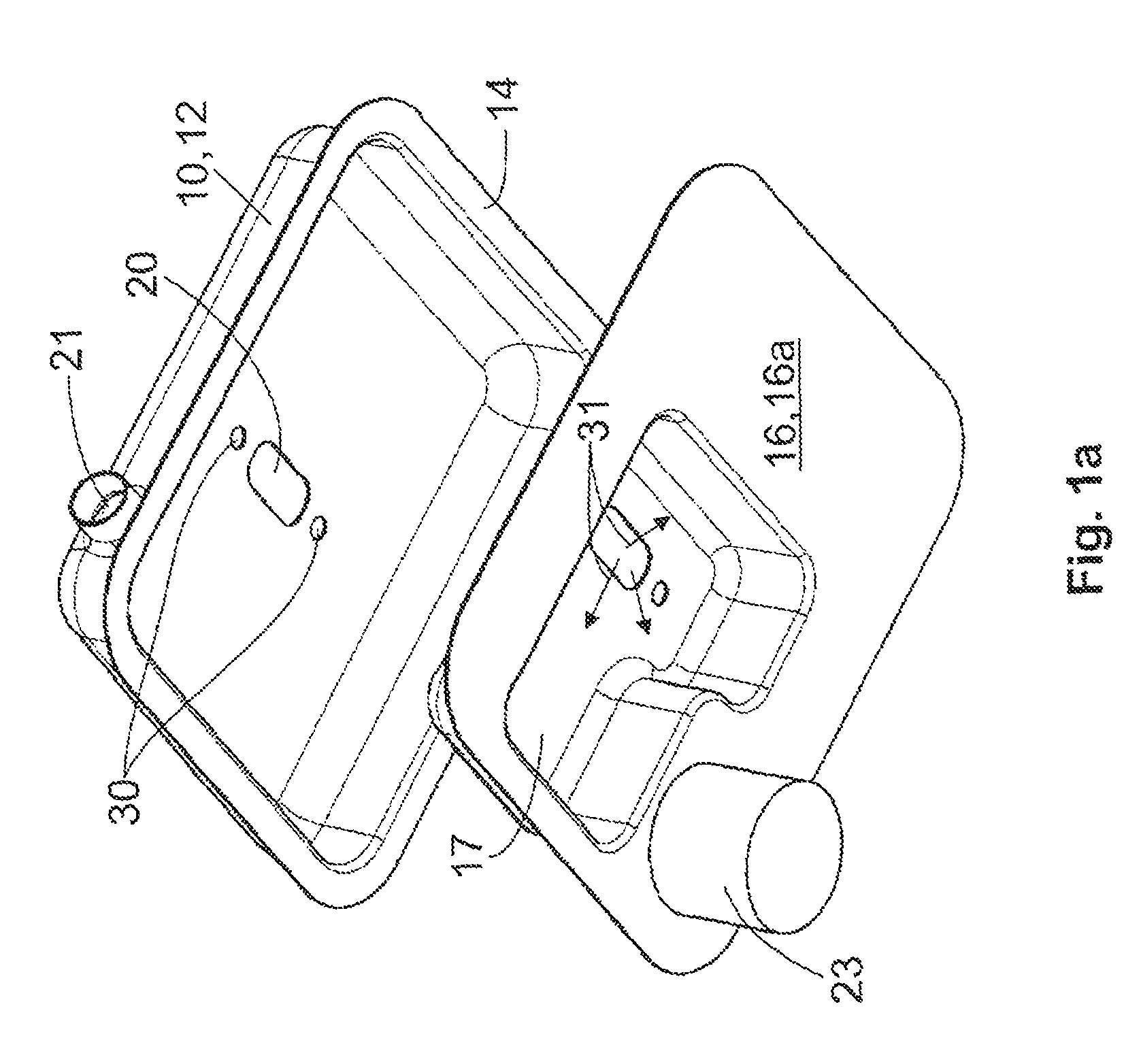
[0029]In FIG. 1a the rear shell 12 of the outer housing 10 of the exhaust system 100 according to the invention is shown with the intermediate shell 16 in perspective representation. In this view the complete front side 16a of the intermediate shell 16 is visible. Here, the moulded prechamber 17 protrudes from the back 16b of the intermediate shell 16. Through this protruding prechamber 17 the exhaust port 19 is formed between the intermediate shell 16 and the rear shell 12. The exhaust gas originating from the combustion chamber (see Arrow 31) enters the exhaust system through an exhaust inlet aperture 20 that is designed oval or rectangular. This exhaust inlet aperture 20 is arranged in the rear shell 12. To the left and right of the inlet aperture 20 apertures 30 for one or several fasteners can be provided which serve for the fastening of the exhaust system 100 to the internal combustion engine. The fasteners not shown protrude through the interior space of the exhaust system 10...


PUM


Abstract

An exhaust system for an internal combustion engine includes an outer housing having a front shell and a rear shell, a prechamber in which exhaust gas from the combustion chamber enters, and an intermediate shell having a front and back as well as a catalytic converter holder. A catalytic converter element is arranged on the catalytic converter holder where an exhaust port directs exhaust gas from the catalytic converter element. To place the center of gravity of the exhaust system near the internal combustion engine or cylinder, the intermediate shell forms the prechamber and the exhaust port.

Description

TECHNICAL AREA[0001]The present invention relates to an exhaust system for an internal combustion engine according to the preamble of claim 1. Such exhaust systems can be used with a four-stroke or a two-stroke petrol engine. Because of the compact design of the exhaust system it can also be used for hand-operated or hand-held implements such as for instance petrol engine-driven disc grinders, chain saws, hedge clippers or such like. Exhaust systems of this type have an outer housing which contains at least a front shell and a rear shell. In addition a prechamber is provided which the exhaust gas enters from the combustion chamber. In addition, at least one intermediate shell having a front side and a rear side and at least one catalytic converter holder can be present, while a catalytic converter element for cleaning the exhaust gas is arranged on the catalytic converter holder. In addition, the exhaust system is equipped with an exhaust port from which the exhaust gas is directed ...

Claims


Application Information

Patent Timeline
Patent Type & Authority Patents(United States)
IPC IPC(8): F01N3/00F01N13/18
CPCF01N3/2885F01N13/1888F01N13/1833F01N2590/06
Inventor KELLERMANN, CHRISTIAN
Owner DOLMAR
Features
  • R&D
  • Intellectual Property
  • Life Sciences
  • Materials
  • Tech Scout
  • Unparalleled Data Quality
  • Higher Quality Content
  • 60% Fewer Hallucinations
Learn More