
Heating device for a battery and battery assembly having the same

a technology of heat generation device and battery assembly, which is applied in the direction of lighting and heating apparatus, cell components, and maintenance/service of primary cells, etc., can solve the problem of sharp reduction of the performance of the battery to generate electricity

Active Publication Date: 2011-12-06
E M W ENERGY CO LTD
View PDF7 Cites 4 Cited by
  • Summary
  • Abstract
  • Description
  • Claims
  • Application Information

AI Technical Summary

Benefits of technology

"The present invention provides a heat-generating device for a battery that can activate the internal materials of the battery even at low temperature using heat generated within the battery. The device includes a heat-generating unit positioned on one side of the battery and configured to generate heat through a reaction with air. The heating element can be made of metal, metallic salt, or its derivatives which react with oxygen or water, or in powder form. The device can maintain the internal temperature of the battery at -30 to -60°C. The battery assembly includes a cathode unit, an anode unit, and a heat-generating unit positioned on an opposite side of the cathode unit and configured to generate heat through a reaction with air. The heat-generating unit can control the cathode and anode units so that they reach or maintain an activation temperature condition. The invention provides an advantage in that the temperature of an internal space of the battery can be maintained so that electricity can be generated at low temperature conditions. Additionally, there is no need for an additional construction for supplying air and installation is convenient."

Problems solved by technology

This because if temperature is low, the activation ability of internal materials of the battery is low, with the result that the performance of the battery to generate electricity is sharply reduced.

Method used


Image

  • Heating device for a battery and battery assembly having the same
  • Heating device for a battery and battery assembly having the same
  • Heating device for a battery and battery assembly having the same

Examples


Embodiment Construction

[0023]Preferred embodiments of the present invention are described in detail with reference to the accompanying drawings, but the present invention is not limited thereto.

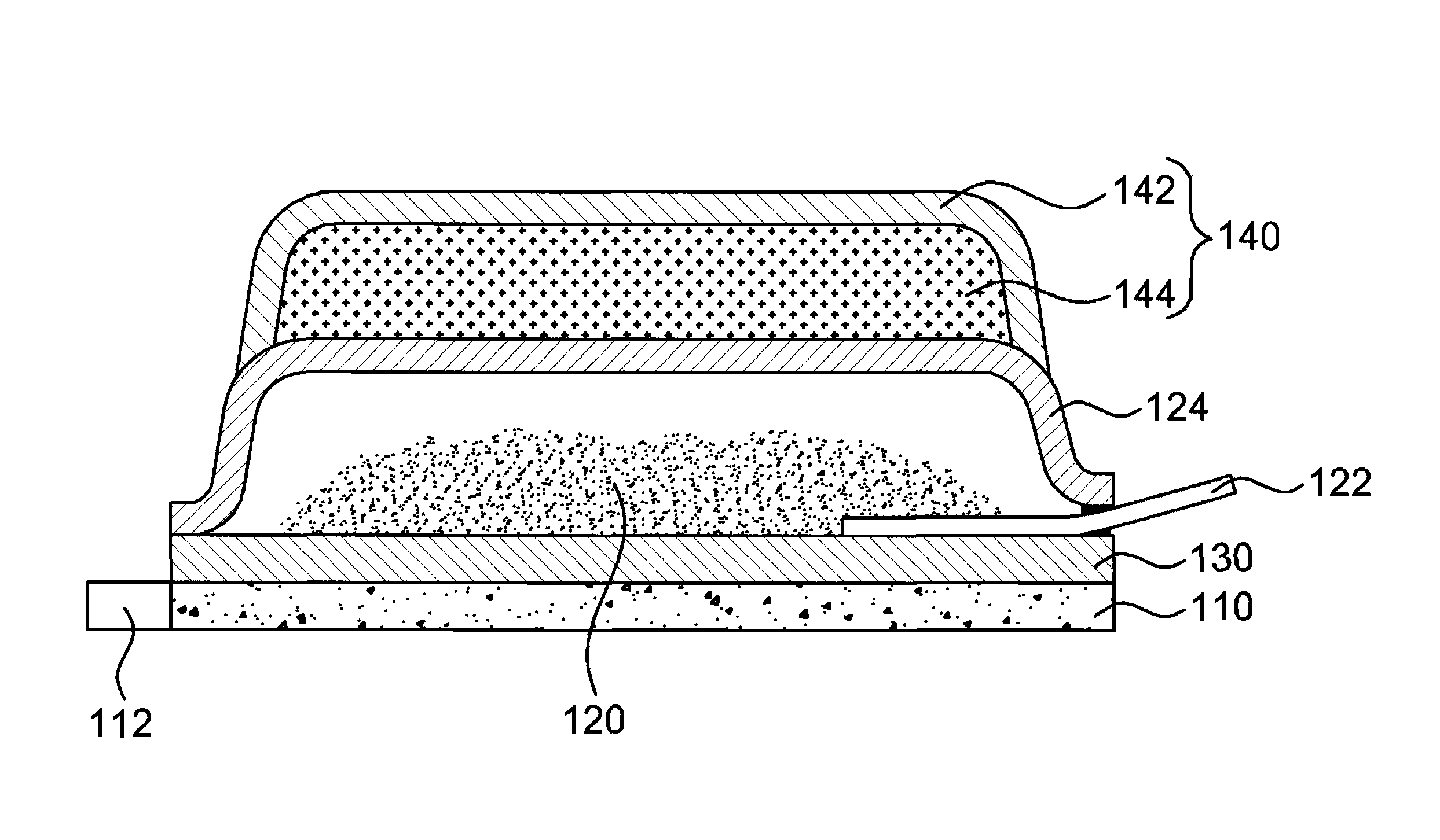
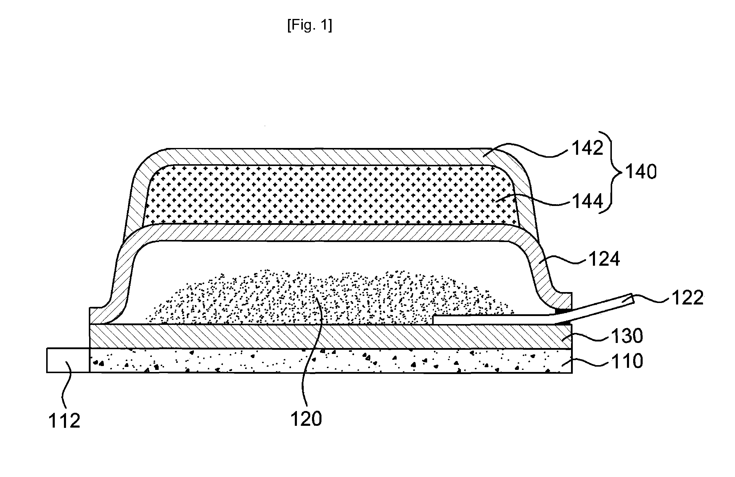
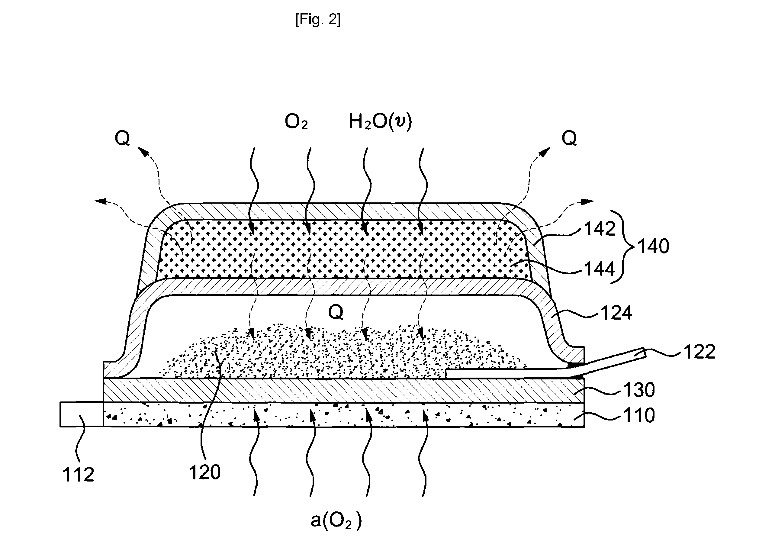
[0024]FIG. 1 is a cross-sectional view showing a battery assembly equipped with a heat-generating device for a battery according to the present invention. As shown in FIG. 1, the battery assembly 100 of the present invention includes a cathode unit110, an anode unit 120, a separator 130, and a heat-generating unit 140.

[0025]The cathode unit 110 includes a cathode terminal 112 and receives electrons via the cathode terminal 112. Furthermore, the anode unit 120 generates electrons and externally outputs the electrons through an anode terminal 122. Further, the anode unit 120 includes an anode casing 124 for protecting the anode unit 120 from the outside. It is preferred that the anode casing 124 be made of a material having a nonconductor property.

[0026]Here, the anode terminal 122 can be constructed in the form of o...


PUM

PropertyMeasurementUnit
temperatureaaaaaaaaaa

Abstract

Disclosed are a heat-generating device for a battery and a battery assembly enabling a battery to stably produce electricity even under low-temperature conditions. The heat-generating device for a battery includes a heating element positioned on one side of the battery and generates heat through a reaction with the air. The heating element comprises a main body generating heat through the reaction with the air, and a supporting body wrapping the main body to adhere to the battery. Accordingly, the internal temperature of the battery can be maintained within possible activation temperature ranges to allow the battery to produce electricity, thereby making the battery performance sustainable under low-temperature conditions.

Description

CROSS-REFERENCE TO RELATED APPLICATIONS[0001]This patent application is a U.S. National Phase application under 35 U.S.C. §371 of International Application No. PCT / KR2009 / 000344, filed on Jan. 22, 2009, entitled HEAT-GENERATING DEVICE FOR BATTERY AND BATTERY ASSEMBLY INCLUDING SAME, which claims priority to Korean patent application number 10-2008-0008167, filed Jan. 25, 2008.TECHNICAL FIELD[0002]The present invention relates to a heat-generating device for a battery and a battery assembly and, more particularly, to a heat-generating device for a battery maintaining the activation of the battery even at low temperature conditions and a battery assembly including the same.BACKGROUND ART[0003]There is a tendency that recent electronic devices are gradually reduced in size so that they can be easily carried. Furthermore, users require more functions. In order to meet the requirements of the users, the electronic devices are being developed to perform more functions. In order to carry t...

Claims


Application Information

Patent Timeline
Patent Type & Authority Patents(United States)
IPC IPC(8): H01M8/02F24V30/00
CPCH01M6/5038H01M10/5006H01M10/5012F24J1/00H01M10/5091H01M12/06C09K5/18H01M10/5053H01M10/615H01M10/6595H01M10/623H01M10/6554F24V30/00Y02E60/10
Inventor RYOU, BYUNG HOONKONG, JAE KYUNG
Owner E M W ENERGY CO LTD
Learn More