Filament lamp

a filament or filament-type technology, applied in the field of filament lamps, can solve the problems of filament or two internal leads being electrically short, the size of the lamp cannot be increased, and the filament or two internal leads cannot be positioned accurately

Active Publication Date: 2011-12-06
USHIO DENKI KK
View PDF10 Cites 3 Cited by
  • Summary
  • Abstract
  • Description
  • Claims
  • Application Information

AI Technical Summary

Benefits of technology

[0007]A primary object of the present invention is to provide a filament lamp having a plurality of independent power supply pathways in which the various problems, such as the positional deviation of a filament and short-circuiting, are efficiently prevented despite the presence of the complicated power supply pathways.
[0011]This invention provides a structure in which the first housing space for housing the filaments and the second housing space for housing the internal leads for supplying electricity are paired and extend in the axial direction. Therefore, the problem that an internal lead and a filament or another lead electrically short to each other can be solved or reduced. Moreover, since the filaments can be held in the first housing space in which there exists no internal lead, the filaments can be positioned accurately.

Problems solved by technology

On the other hand, the size of a lamp cannot be increased, and there is a demand for reducing the size thereof instead.
For this reason, there occurs a problem that an internal lead and a filament or two internal leads electrically short to each other or that a filament comes off a specified position.
As a result, the abovementioned problems occur.

Method used


Image

  • Filament lamp
  • Filament lamp
  • Filament lamp

Examples


Embodiment Construction

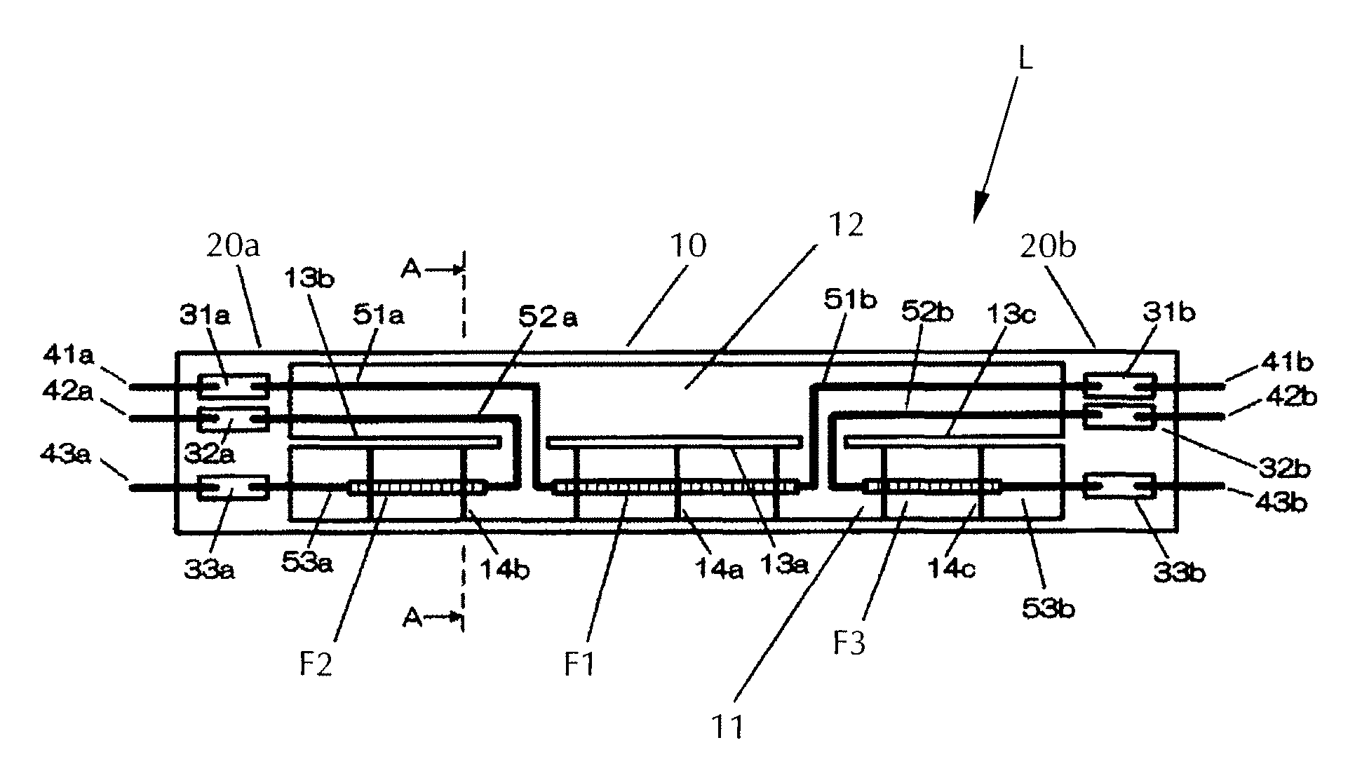
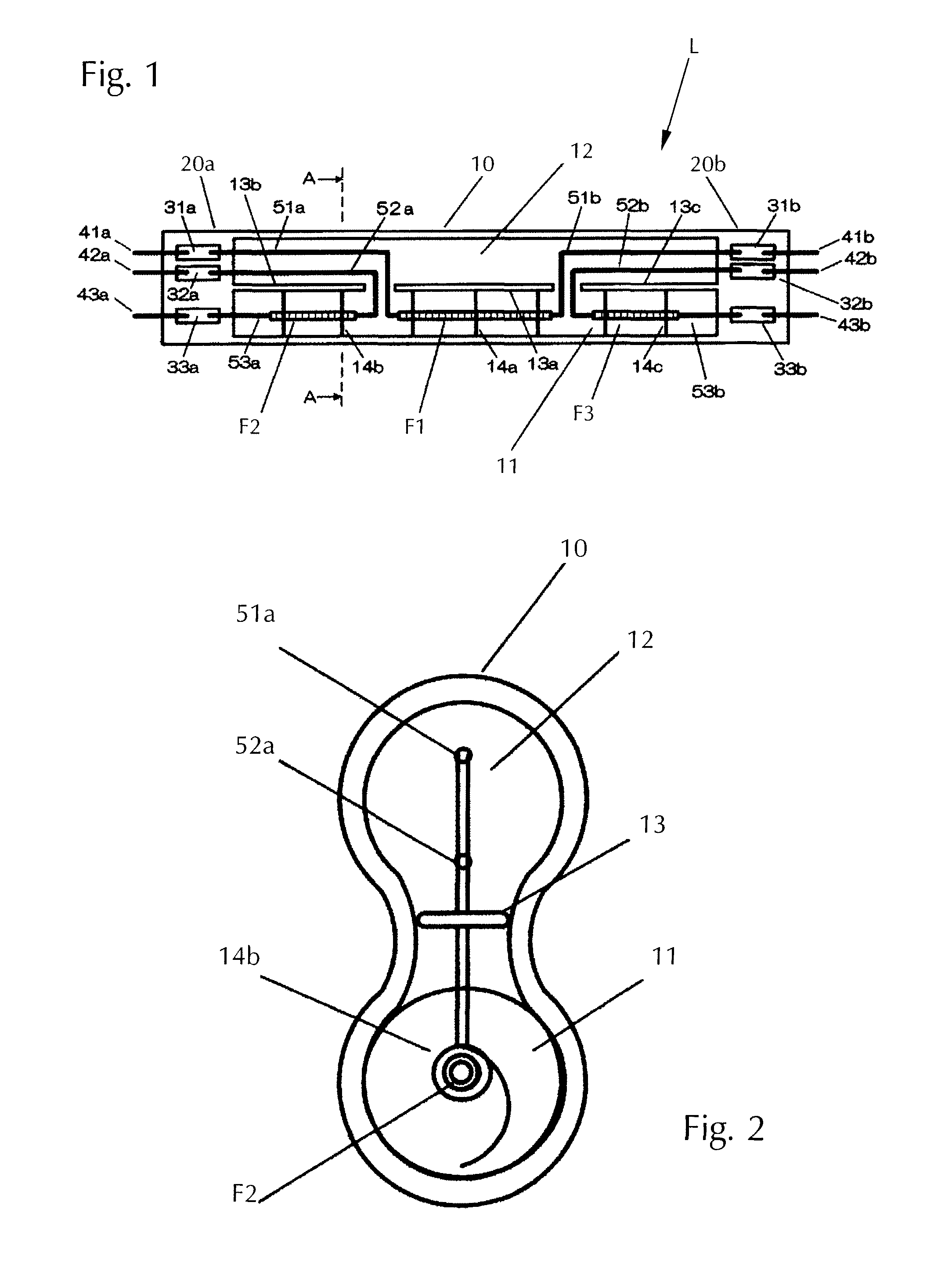
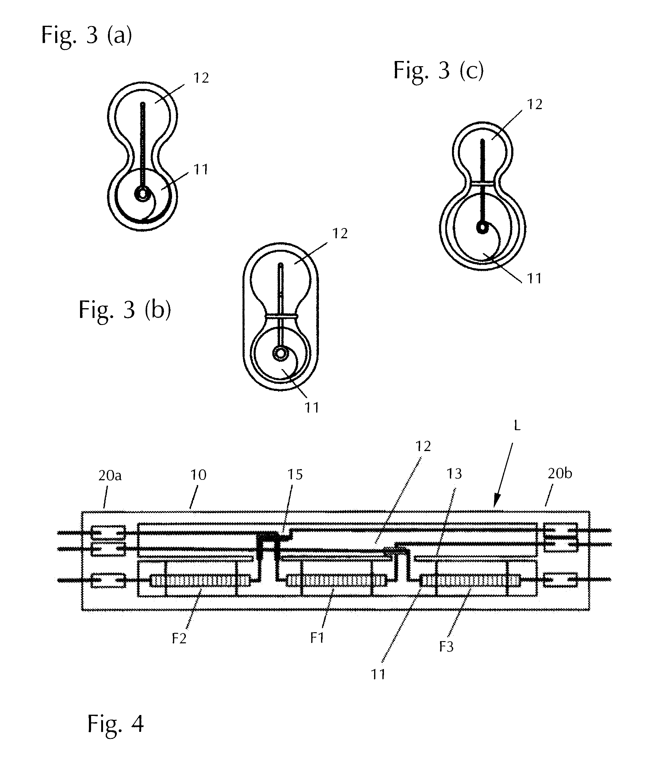
[0018]FIG. 1 shows the entire configuration of the filament lamp L according to the present invention which is comprised of a straight-tube type luminous part 10 and sealing parts 20a, 20b formed on opposite ends of luminous part 10. The luminous part 10 is formed of a first housing space 11 and a second housing space 12 as described below, and its cross section is substantially gourd-shaped as a whole (by which is meant that it is formed of sections that are at least internally circular that contain the first and second housing spaces 11, 12 and are connected to each other by a narrower neck portion, the circular sections not necessarily being of the same size; cf. FIG. 3(c)).

[0019]The first housing space 11 and the second housing space 12 are spatially linked with each other. Both spaces are paired and extend in the axial direction. Inside the first housing space 11 are disposed multiple filaments F1, F2, F3. Specifically, the filament F1 is disposed at the center in the longitudi...


PUM


Abstract

To provide the structure of a filament lamp having a plurality of independent power supply pathways, the structure being capable of preventing the power supply pathways from electrically shorting to each other, a filament lamp formed of a straight-tube shaped luminous part having multiple filaments (F1, F2, F3) divided in the axial direction, and sealing parts (20) on each of opposite ends of the luminous part (10) in which are embedded metal foils (31, 32, 33) corresponding to the number of filaments in an aligned manner, and leads for supplying electricity independently to each filament, the luminous part (10) having a first housing space (11) for housing the filaments and a second housing space (12) for housing the leads (51, 52, 53), the housing spaces be connected and extending in the axial direction.

Description

BACKGROUND OF THE INVENTION[0001]1. Field of Invention[0002]The present invention relates to a filament lamp, particularly to a filament lamp for heating an object to be treated.[0003]2. Description of Related Art[0004]The production steps for solar cells include a thermal diffusion step for diffusing a P type semiconductor and a baking step for baking silver paste to make electrode material. In both steps, a semiconductor wafer and a glass substrate are heated to a high temperature of around 800° C. to 900° C. using a thermal diffusion furnace and a baking furnace, respectively.[0005]In such a heating device, an object to be treated must be heated uniformly in order to avoid a locational variation of temperature. For this reason, what has been proposed is a structure capable of providing multiple power supply pathways inside the luminous tube of a filament lamp as a light source and independently supplying a desired amount of electricity to each pathway (Japanese Laid-open Applicat...

Claims


Application Information

Patent Timeline
Patent Type & Authority Patents(United States)
IPC IPC(8): H01K9/00
CPCH01K1/16H01K1/24H01K1/28H01K1/40H01K7/00H01K9/08H05B6/129H01K5/02H01L21/26H01L21/02
Inventor TANINO, KENJIMIZUKAWA, YOICHI
Owner USHIO DENKI KK
Why Eureka
Try Eureka