Driving assist method and driving assist apparatus for vehicle

a technology for driving assistance and vehicles, applied in brake systems, process and machine control, instruments, etc., can solve the problem that the driver cannot predict the actual position where the vehicle will come to a stop, and achieve the effect of quick adjustment of the operation of the vehicl

Active Publication Date: 2011-12-06
AISIN AW CO LTD
View PDF14 Cites 34 Cited by
  • Summary
  • Abstract
  • Description
  • Claims
  • Application Information

AI Technical Summary

Benefits of technology

[0007]Accordingly, it is an object of the present invention to provide a driving assist method and a driving assist apparatus for displaying a position at which the vehicle speed will become a predetermined speed according to deceleration of the vehicle, to assist the driver to quickly adjust his / her operation of the vehicle.
[0008]To solve the problems described above, the present invention provides a driving assist method for a vehicle comprising the steps of calculating a position at which a vehicle speed will have decelerated to a predetermined speed and superimposing that calculated position as an arrival indicator on a map display. Therefore, the driver may observe the position at which the vehicle speed will become the predetermined speed with braking of the vehicle, so that the driver may quickly adjust his / her operation of the vehicle.
[0009]The driving (braking) assist method of the present invention includes the steps of locating an object in front of the vehicle, specifying the position of the located object, calculating the position at which the vehicle speed will become a predetermined speed based on deceleration of the vehicle, generating an arrival indicator based on that calculated position of the vehicle, and displaying the arrival indicator. Therefore, the driver may visually determine the distance, calculated for the predetermined speed, the vehicle will be from the location of the object, again allowing the driver to quickly adjust his or her operation of the vehicle.

Problems solved by technology

However, the conventional apparatus described above simply informs the driver of the existence of the obstacle and the driver brakes the vehicle, so that the driver cannot predict the actual position where the vehicle will come to a stop.

Method used


Image

  • Driving assist method and driving assist apparatus for vehicle
  • Driving assist method and driving assist apparatus for vehicle
  • Driving assist method and driving assist apparatus for vehicle

Examples


Embodiment Construction

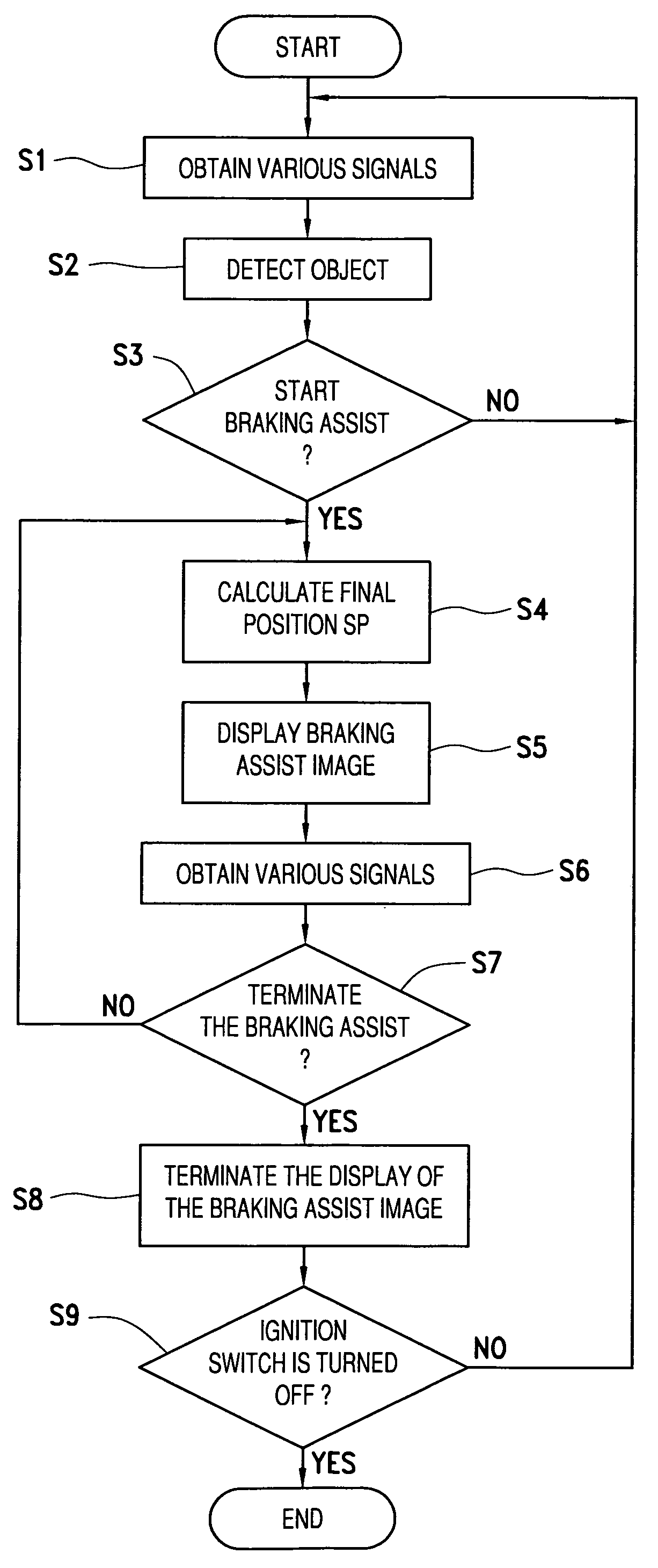
[0031]An embodiment of the present invention is described with reference to FIGS. 1A to 5 below.

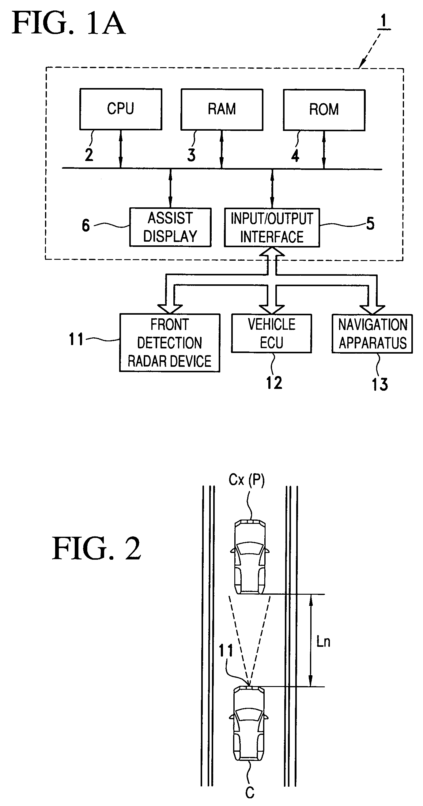
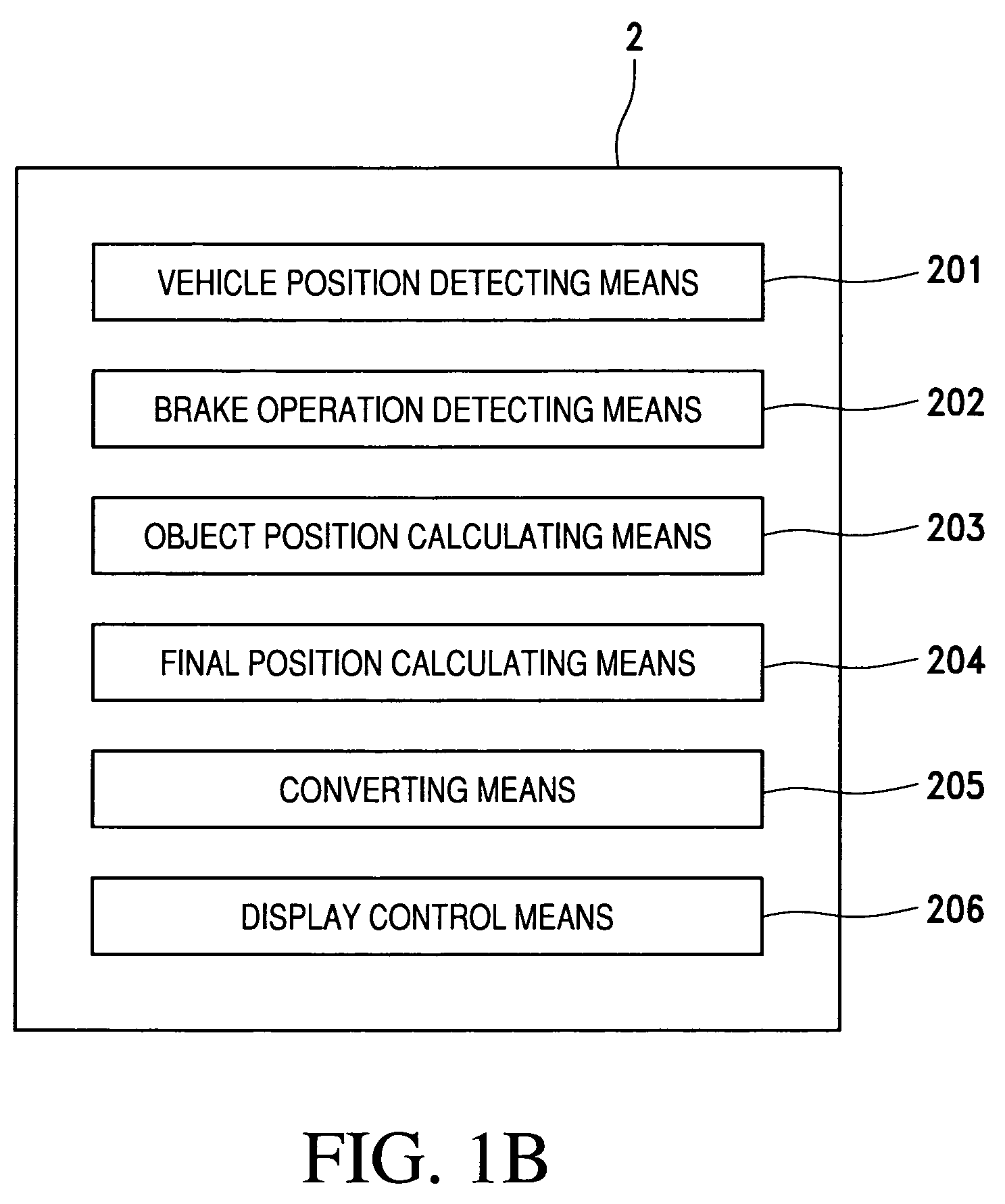
[0032]FIG. 1A is a block diagram, in accordance with an embodiment of the present invention, of a driving assist apparatus mounted on a vehicle. The driving assist apparatus 1 in FIG. 1A, as shown in FIG. 1B, includes a CPU 2 with vehicle position detecting means 201, brake operation detecting means 202, object position calculating means 203, final position calculating means 204, converting means 205, and display control means 206. The driving assist apparatus 1 further includes, as shown in FIGS. 1A and 1B, an RAM 3 temporarily storing calculations by the CPU 2, a ROM 4 with various stored driving assist programs such as a driving assist program for braking, an input / output interface 5, and an assist display 6.

[0033]The CPU 2 connects to a front detection radar device 11 through the input / output interface 5. In the present embodiment, the front detection radar device 11 is a millimeter w...


PUM


Abstract

Responsive to braking, a CPU of a driving assist apparatus calculates an average deceleration of the vehicle and then calculates a braking distance. The CPU further calculates a final position at which the vehicle will come to a stop, on the basis of the braking distance. The CPU next activates an assist display for display a map including, superimposed thereon, the route to the final position and an arrival indicator indicating the stop (final) position of the vehicle.

Description

INCORPORATION BY REFERENCE[0001]The disclosure of Japanese Patent Application No. 2005-337680 filed on Nov. 22, 2005, including the specification, drawings and abstract thereof, is incorporated herein by reference in its entirety.BACKGROUND OF THE INVENTION[0002]1. Field of the Invention[0003]The present invention relates to a driving assist method and apparatus for a vehicle and, more particularly, to a braking assist method and apparatus.[0004]2. Description of the Related Art[0005]Driving assist apparatus for assisting driving operations are well known. A driving assist apparatus, for example as described in Japanese Unexamined Patent Application Publication No. 2002-163795, estimates a braking distance for a vehicle and gives obstacle information and driving guidance to a driver to avoid crashing against an obstacle ahead. The driving assist apparatus also detects an obstacle ahead, calculates the distance to the obstacle, as well as the braking distance of the vehicle, and aler...

Claims


Application Information

Patent Timeline
Patent Type & Authority Patents(United States)
IPC IPC(8): G05D1/00B60T8/32G06F17/00G06G7/78
CPCB60T7/22G01C21/26G08G1/161G08G1/163
Inventor YAMAMOTO, YUKIOSHIBATA, YUMIMARUYAMA, KATSUYA
Owner AISIN AW CO LTD
Why Eureka
Try Eureka