Method and system for the cursor-aided manipulation of flight plans in two and three dimensional displays

a flight plan and display technology, applied in the field of aircraft flight path design, can solve the problems of deviation between the actual position of the aircraft and the intended position, all navigation systems have uncertainty in their ability to determine, and all pilots and automated flight systems have limitations in their ability to track an intended flight path, so as to avoid terrain conflicts

Active Publication Date: 2011-12-06
ROCKWELL COLLINS INC
View PDF9 Cites 47 Cited by
  • Summary
  • Abstract
  • Description
  • Claims
  • Application Information

AI Technical Summary

Benefits of technology

[0019]In a broad aspect, the present invention is a method of creating and modifying a flight plan to avoid terrain conflicts using a cursor control device and a display to represent the flight plan in the context of terrain. The method includes inserting waypoints, including origin and destination waypoints, into a flight plan using a cursor control device to position the waypoints in a display and commanding a flight management system (FMS) to connect the waypoints into a flight plan. The flight plan is drawn in the context of terrain on a display where conflicts between the

Problems solved by technology

All navigation systems have an uncertainty in their ability to determine the position of the aircraft.
All pilots and automated flight systems have limitations in their ability to track an intended flight path.
These limitations result in deviations between the actual position of the aircraft versus the intended position of the aircraft.
The total system error (“TSE”) is the combination of uncertainty in the navigation system and the flight technical error of the pilot or automated flight system.
Dead-reckoning is highly inaccurate in windy conditions because the pilot cannot accurately determine the actual ground speed or aircraft track (which differ from airspeed and heading due to the velocity of the wind).
However, even the best, and most expensive, inertial navigation systems suffer from position errors that increase over time (typically with a drift rate of 2 nautical miles or more per hour).
Thus, operating by dead-reckoning can result in a very large TSE.
While t

Method used


Image

  • Method and system for the cursor-aided manipulation of flight plans in two and three dimensional displays
  • Method and system for the cursor-aided manipulation of flight plans in two and three dimensional displays
  • Method and system for the cursor-aided manipulation of flight plans in two and three dimensional displays

Examples


Embodiment Construction

[0050]Referring to FIG. 4 (Prior Art), a cross-sectional view of the intended flight path within the obstacle clearance surface (OCS), due to the large total system error that is possible under IFR is shown. The aircraft could be anywhere within the boundaries of the OCS.

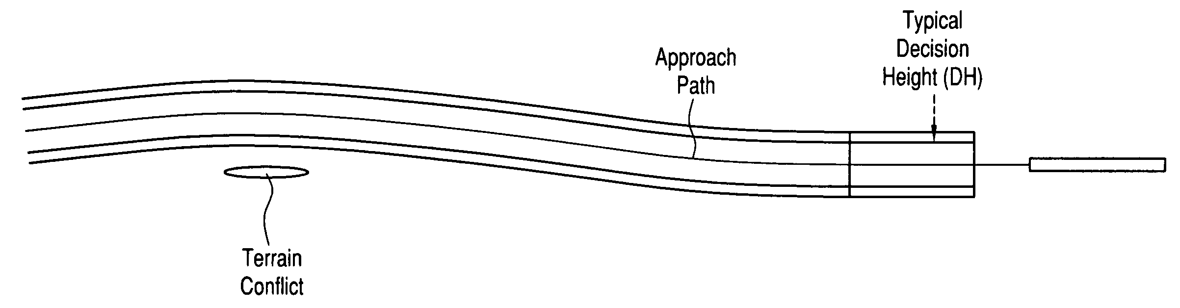
[0051]As shown in FIG. 5 (Prior Art), a top down view of the intended flight path within the OCS, TERPS assumes that the aircraft will follow a straight-in path to the aircraft on most final approaches. Because the top of the terrain projects into the OCS, the pilot must fly the final approach with sufficient visibility to see the runway environment prior to reaching the terrain cell of interest—therefore MDA is before the terrain cell (well before a more typical decision height for a precision landing).

[0052]Referring to FIG. 6, the goal of the present invention is to bend the intended flight path around the terrain cell of interest; however, this is very challenging. The present invention allows the pilot to gener...


PUM


Abstract

A method of creating and modifying a flight plan using a cursor control device and a display to represent the flight plan in the context of terrain. The method includes inserting waypoints, including origin and destination waypoints, into a flight plan using a cursor control device to position the waypoints in a display and commanding a flight management system (FMS) to connect the waypoints into a flight plan. The flight plan is drawn in the context of terrain on a display where conflicts between the flight plan and terrain are indicated. Selected elements of the flight plan are selected with a cursor control device and the selected elements are dragged to new positions on the display until terrain conflicts are eliminated, thus generating a modified flight plan. The modified flight plan is reviewed in the context of terrain to determine its acceptability and making further modifications thereof if desired. The modified flight plan is selected from the review thereof, the modified flight having no conflicts with terrain. Finally, the modified flight plan is activated using the FMS.

Description

BACKGROUND OF THE INVENTION[0001]1. Field of the Invention[0002]The present invention relates generally to aircraft flight path design, and more particularly to cursor-aided manipulation of flight plans in flight displays.[0003]2. Description of the Related Art[0004]There are two basic sets of rules for flight operations, Visual Flight Rules (VFR) and Instrument Flight Rules (IFR). Visual Meteorological Conditions (VMC) are those weather conditions in which pilots have sufficient visibility to maintain visual separation from terrain, obstacles, and other aircraft. Instrument Meteorological Conditions (IMC) are those weather conditions in which pilots cannot maintain visual separation from terrain, obstacles, and other aircraft.[0005]Under Visual Flight Rules (VFR), the pilot maintains separation from terrain, obstacles, and other aircraft by visual reference to the environment surrounding the aircraft. The guiding principle for VFR is “See and Avoid”. Under Instrument Flight Rules (...

Claims


Application Information

Patent Timeline
IPC IPC(8): G06G7/72
CPCG08G5/0034G08G5/0039G08G5/0021G08G5/0026
Inventor MCCUSKER, PATRICK D.
Owner ROCKWELL COLLINS INC
Why Eureka
Try Eureka