Decoupling groove for pneumatic tire tread

a pneumatic tire and groove technology, applied in the field of side tread decoupling grooves, can solve the problems of uneven tread wear, sharp edges, and high wear erosion in the shoulder region, and achieve the effect of reducing the risk of slipping and slipping, and improving the safety of users

Inactive Publication Date: 2011-12-13
THE GOODYEAR TIRE & RUBBER CO
View PDF13 Cites 9 Cited by
  • Summary
  • Abstract
  • Description
  • Claims
  • Application Information

AI Technical Summary

Benefits of technology

[0010]According to yet another aspect of the present invention, a lateral projection further provides protection from shoulder damage.

Problems solved by technology

These conventional sharp edges, during normal use, may exhibit irregular tread wear.
Thus, high wear erosion may be common in the shoulder region of such a tread.

Method used


Image

  • Decoupling groove for pneumatic tire tread
  • Decoupling groove for pneumatic tire tread
  • Decoupling groove for pneumatic tire tread

Examples


Embodiment Construction

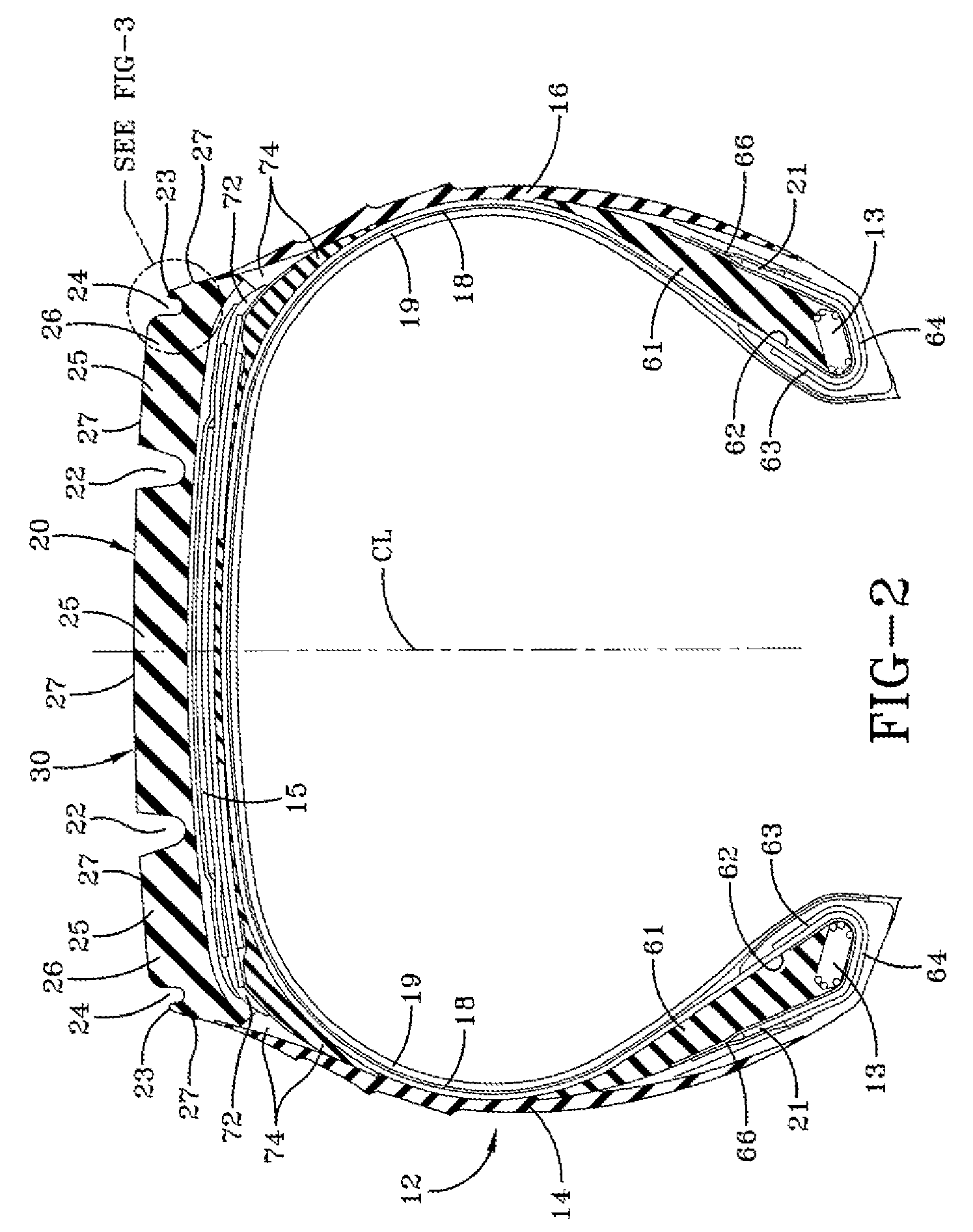
[0030]FIGS. 1 and 2 show an example tire 10 for use with the present invention. The tire 10 has a tread 20 and a casing 12. The casing 12 has two sidewalls 14, 16, one or more radial plies 18 extending from, and wrapped about, two annular beads 13, and a belt reinforcement structure 15 located radially between the tread 20 and the ply or plies 18.

[0031]The plies 18 and the belt reinforcement structure 15 may be cord reinforced elastomeric material. The cords may be, for example, steel wire filaments and the elastomer may be, for example, a vulcanized rubber material. Similarly, the annular beads 13 may have steel wires wrapped into a bundle forming a bead core. A liner component 19, for example a halobutyl rubber, may form a somewhat air impervious chamber to contain the air pressure when the tire 10 is inflated.

[0032]The tire 10 may further include an elastomeric apex 61 radially disposed above each bead 13. A turnup 21 of the ply 18 in each bead area may be reinforced with a flipp...


PUM


Abstract

A pneumatic radial ply truck tire for use on medium truck trailers includes a tread, a casing with two sidewalls, one or more radial plies extending from, and wrapped about, two annular beads, and a belt reinforcement structure located radially between the tread and the one or more radial plies. The tread includes a plurality of circumferentially extending tread grooves, a pair of circumferentially extending shoulder ribs, a pair of radially recessed ribs being radially recessed and non-road contacting under static load disposed at a lateral edge of the shoulder ribs, and a pair of circumferentially extending decoupling grooves. Each decoupling groove defines a transition between a corresponding shoulder rib and a corresponding recessed rib. A lateral edge of one of the shoulder ribs has a first radius of curvature forming a transition from a radially outer surface of the shoulder rib to a first side surface of the corresponding decoupling groove. A base surface of the decoupling groove has a second radius of curvature forming a transition from the first side surface to a second side surface of the decoupling groove. A radially outer surface of the corresponding recessed rib has a third radius of curvature forming a continuous transition from the second side surface to a third outer side surface of the shoulder portion of the tread.

Description

FIELD OF INVENTION[0001]The present invention relates to truck tires and treads for truck tires and, particularly, to side tread decoupling grooves for inhibiting crack propagation from a sidewall to the tread.BACKGROUND OF THE INVENTION[0002]The use of treads specifically designed for truck tires has been directed to various forms of rib-type tires. This non-driving axle exhibits cornering and turning loads as well as straight line running loads. Some skilled in the art believe the tread ribs should ideally have a sharp edge adjacent circumferential grooves to provide improved handling.[0003]These conventional sharp edges, during normal use, may exhibit irregular tread wear. Thus, high wear erosion may be common in the shoulder region of such a tread. One conventional approach may use a laterally located circumferentially continuous rib that, under normal driving conditions, may be in contact with the road. The force or pressure exerted by the lateral rib on the road is less than t...

Claims


Application Information

Patent Timeline
Patent Type & Authority Patents(United States)
IPC IPC(8): B60C11/01B60C11/04
CPCB60C11/01B60C11/0306Y10S152/901B60C2200/06B60C2011/013
Inventor SEVART, JEFFREY LEONBLACKISTON, PAUL KEYSERYAP, PEDROGORDON, LARRY ASHLEY
Owner THE GOODYEAR TIRE & RUBBER CO
Why Eureka
Try Eureka