
Structural dynamic stability for an aircraft

a structural dynamic and aircraft technology, applied in the field of aeronautics, can solve the problems of structural and aerodynamic forces coupling, particularly dangerous types of instability, etc., and achieve the effects of improving structural dynamic stability, reducing the probability of flutter, and facilitating the uncoupling of rotational motion

Active Publication Date: 2011-12-13
BURGESS CALVIN
View PDF8 Cites 8 Cited by
  • Summary
  • Abstract
  • Description
  • Claims
  • Application Information

AI Technical Summary

Benefits of technology

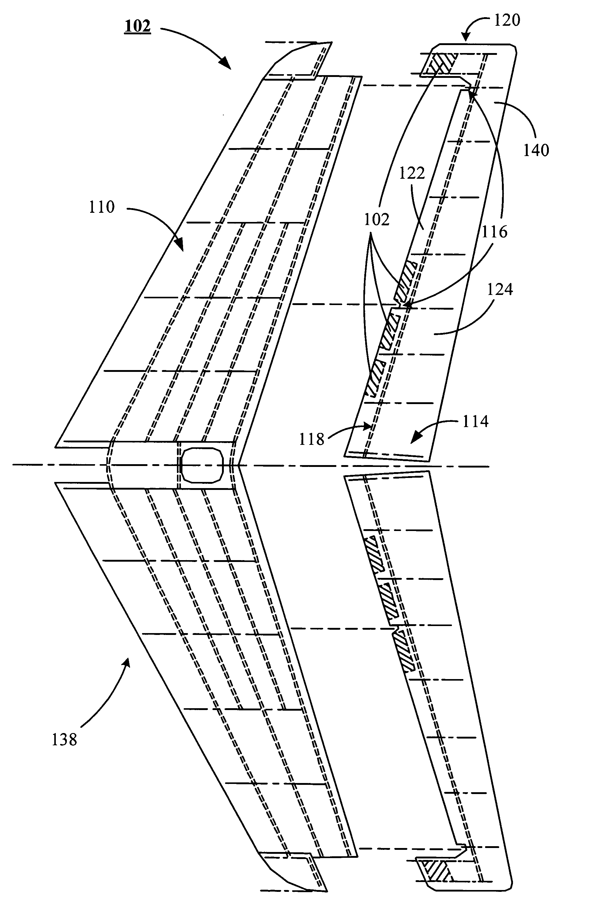
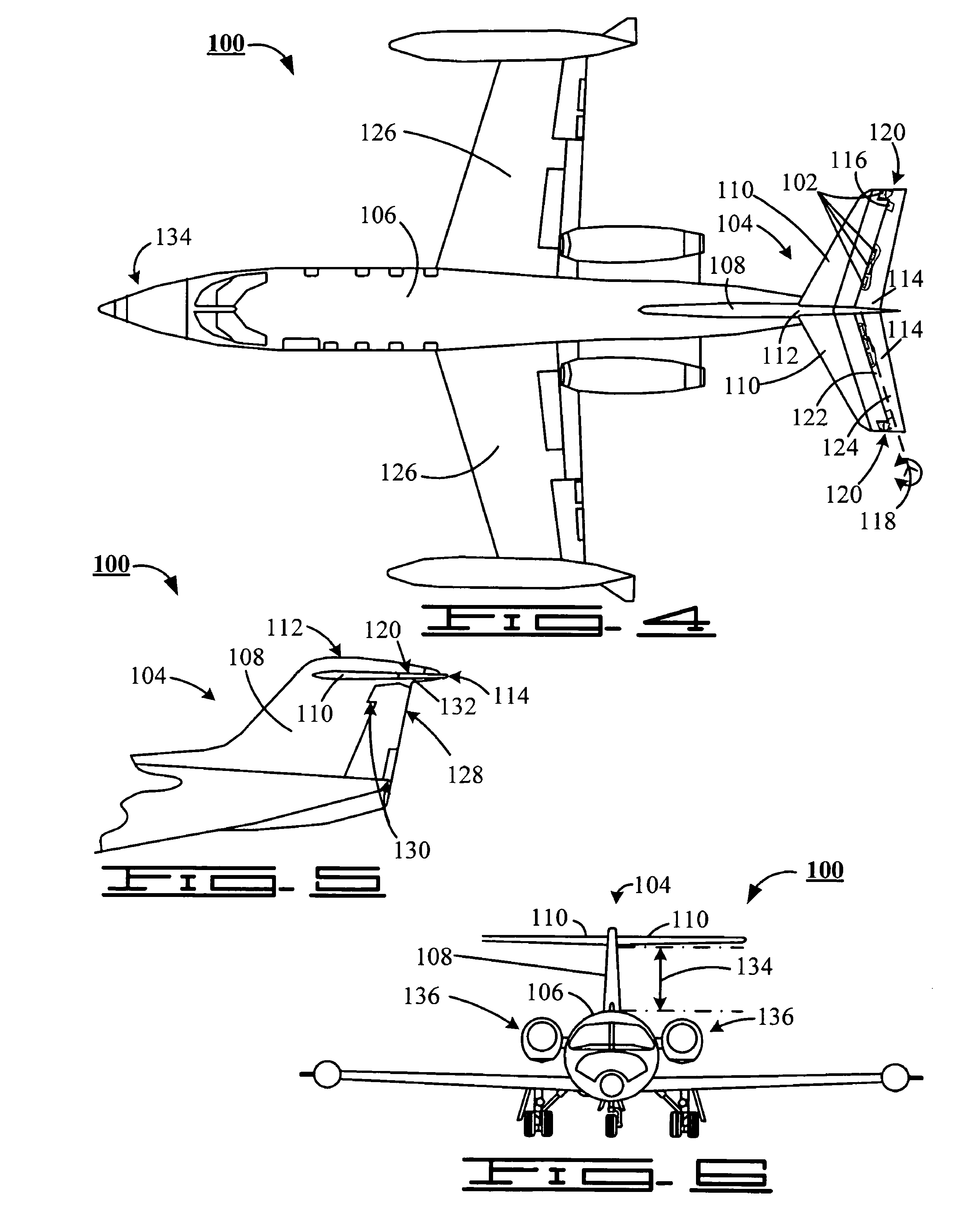
"The patent text describes an improvement to the stability of a Learjet aircraft. The improvement involves adding a tail section with a horizontal stabilizer and a portion of a mass counterbalance weight to the elevator. This weight distribution helps to uncouple the rotational motion of the elevator from the translation motions of the stabilizer, reducing the likelihood of a flutter event. The original mass counterbalance weight is replaced with a new weight that is lighter than the original weight. The new weight is distributed in two parts, with one part located at the front of the elevator and the other part located between the front and the back of the elevator. The total weight of the new weights is greater than the original weight. The method also involves removing the original elevator from the horizontal stabilizer, skin, and mass counterbalance weight."

Problems solved by technology

A particularly dangerous type of instability, and which is typically tested for, is flutter.
Flutter results from a coupling between structural and aerodynamic forces.

Method used


Image

  • Structural dynamic stability for an aircraft
  • Structural dynamic stability for an aircraft
  • Structural dynamic stability for an aircraft

Examples


Embodiment Construction

Reference will now be made in detail to one or more examples of the invention depicted in the accompanying figures. Each example is provided by way of explanation of the invention, and not meant as, nor do they represent, limitations imposed upon the invention. For example, features illustrated or described as part of one embodiment may be used with another embodiment to yield still a different embodiment. Other modifications and variations to the described embodiments are also contemplated and lie within the scope and spirit of the invention.

Preferably, the improvement disclosed herein includes a redistribution of the elevator balance weights so as to provide dynamic balance between the rotation of the elevator and the translation motion of the higher order modes, such as the 28 CPS mode, as well as the translation motion of the lower fundamental modes of vibration.

The original elevator design configuration for 20 and 30 Series Learjets concentrated the elevator balance weight at t...


PUM


Abstract

An improvement and method for improved structural dynamic stability for 20 and 30 Series Learjets are disclosed. The improvement includes a redistribution of the elevator mass balance to uncouple the elevator rotational motion from the stabilizer translation motion for the higher order horizontal frequencies having node lines in the proximity of the mass outboard counterbalance weights. The original tail section includes a rudder, and a horizontal stabilizer supporting an elevator mounted adjacent the rudder. The elevator includes a proximal end adjacent the rudder and a distal end that includes a counterbalance portion. The improvement includes replacement of an original mass counterbalance weight from within the counterbalance portion with a new mass counterbalance weight of less mass, and the inclusion of additional mass counterbalance weights disposed within the elevator and interposed between the proximal end and the counterbalance portion.

Description

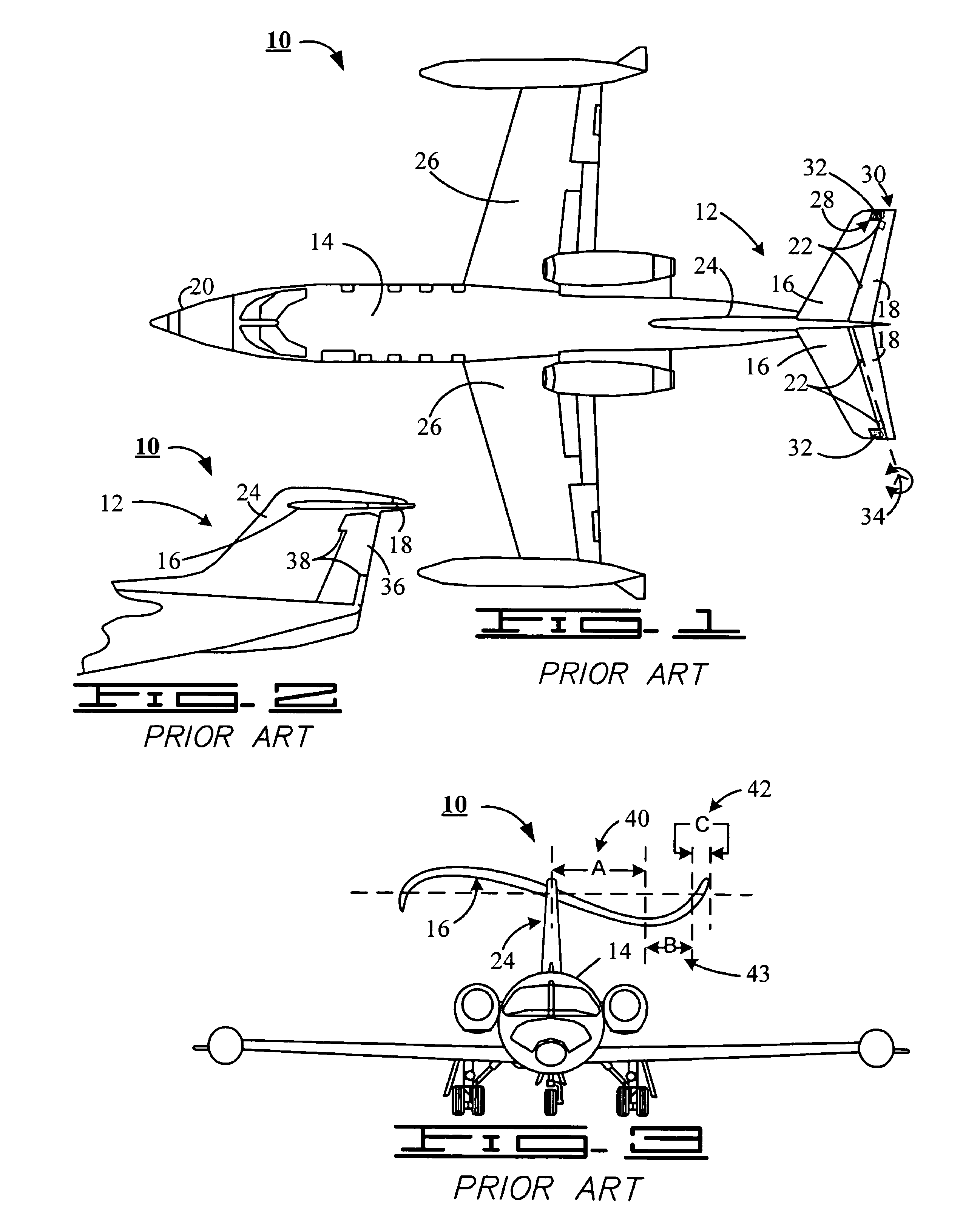
FIELD THE INVENTIONThe claimed invention relates generally to the field of aeronautics and more particularly, but not by way of limitation, to a method and apparatus for improved structural dynamic stability for an aircraft.BACKGROUNDThe determination of a “flight envelope” for an aircraft is an important task typically undertaken by aeronautical engineers during the development and testing phases of aircraft design. Flight testing is performed to evaluate the characteristics of an aircraft and to determine a range of flight conditions in which an aircraft can be operated with safety. A particularly dangerous type of instability, and which is typically tested for, is flutter. Flutter results from a coupling between structural and aerodynamic forces. Flutter is an aerodynamically induced vibration, involving the coupling of two primary modes of vibration or a primary mode with a control rotation mode of vibration such that the aerodynamic forces overcome the structural damping forces...

Claims


Application Information

Patent Timeline
Patent Type & Authority Patents(United States)
IPC IPC(8): B64C17/00
CPCB64C5/02B64C9/02
Inventor BAKER, JOHN
Owner BURGESS CALVIN
Learn More