Surface light source device and image display device

a light source device and surface light source technology, applied in the field of surface light source devices and image display devices, can solve the problems of increasing costs, reducing light use efficiency, and high cost of optical films, and achieves the effects of reducing the number of light sources, shortening the distance between light sources, and low cos

Inactive Publication Date: 2011-12-13
SONY CORP
View PDF9 Cites 13 Cited by
  • Summary
  • Abstract
  • Description
  • Claims
  • Application Information

AI Technical Summary

Benefits of technology

In the surface light source device disclosed in Patent Document 1, directivity occurs in light emitted to the light-emitting surface side due to the function of the prism array. It is desirable to suppress the directivity of light to be as small as possible in order to realize uniform display as the liquid crystal display device. Therefore, it is usually necessary to stack plural optical films such as diffusion sheets between the prism array and the light-emitting surface to cancel out the directivity of light. However, since this kind of optical film is generally expensive, the costs increase. Additionally, since light sequentially passes through the plural optical films in actual fact, use efficiency of light decreases.
It is desirable to provide a structure in which a surface light source device is allowed to be thin with low costs without making the lamp images conspicuous.
According to the embodiment of the invention, the light control member is inserted between plural light sources and the reflective member, and the rugged structure portion in which geometric shapes in cross section are formed continuously is provided on at least one surface of the light control member, thereby allowing the light control member to have the light-guiding function and thereby guiding light between plural light sources (intermediate position) by using the light-guiding function. As a result, it is possible to reduce the number of light sources and to shorten the distance between the light sources and the diffusing member without making the lamp images conspicuous. Accordingly, the surface light source device is allowed to be thin with low costs. Additionally, an image display device is formed by combining the surface light source device with a display panel, thereby allowing an image display device to be thin.

Problems solved by technology

However, since this kind of optical film is generally expensive, the costs increase.
Additionally, since light sequentially passes through the plural optical films in actual fact, use efficiency of light decreases.
Accordingly, there is a problem that, for example, slight displacement of lamps is recognized as unevenness of display.
Therefore, there is a problem that it is difficult to obtain mass-production efficiency and the device will be an expensive component.
In the surface light source device disclosed in Patent Document 3, it is difficult to obtain the function of guiding light between adjacent lamps.
Therefore, it is difficult to allow the device to be a thinner in actual fact.

Method used


Image

  • Surface light source device and image display device
  • Surface light source device and image display device
  • Surface light source device and image display device

Examples


first embodiment

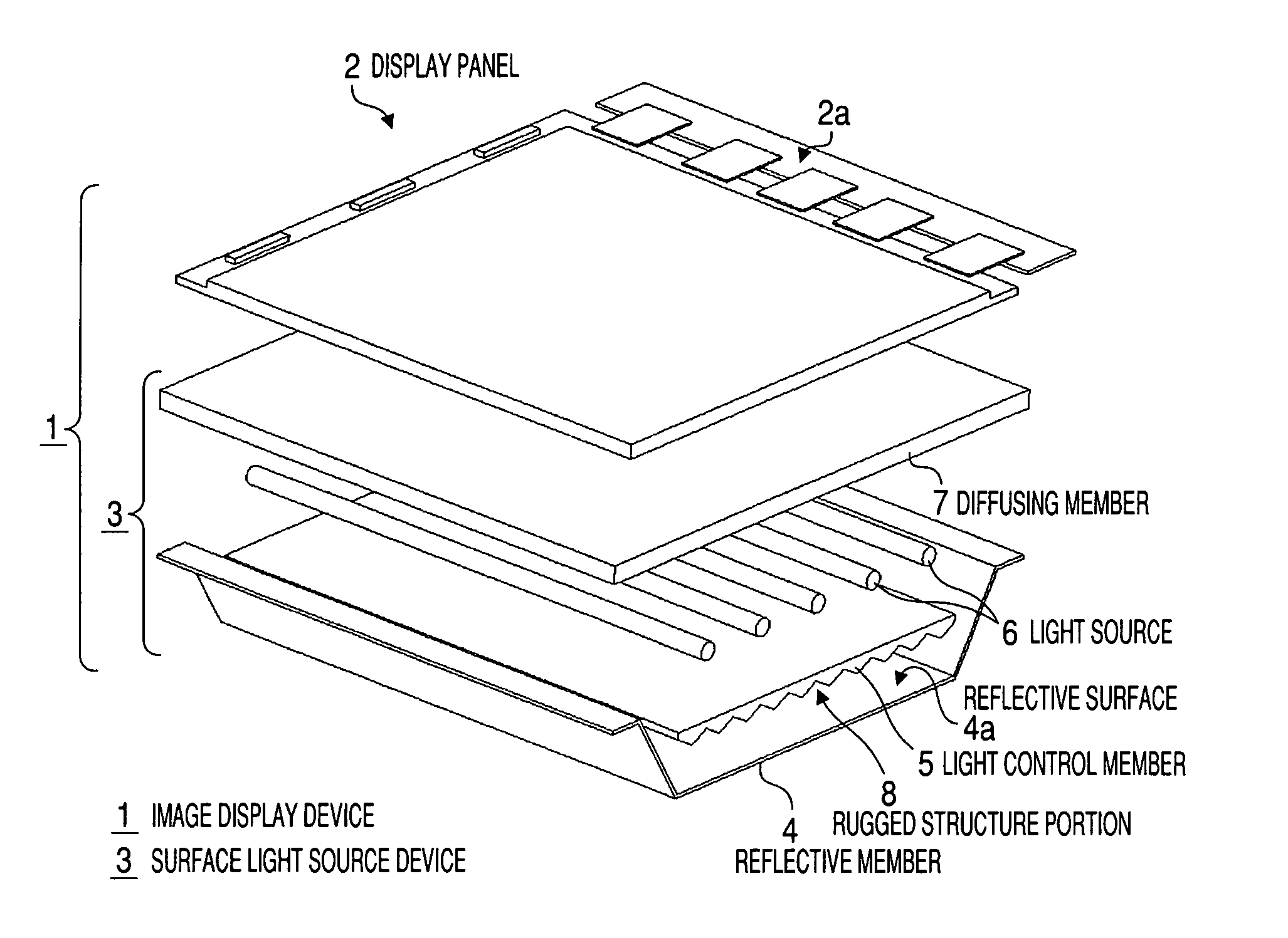
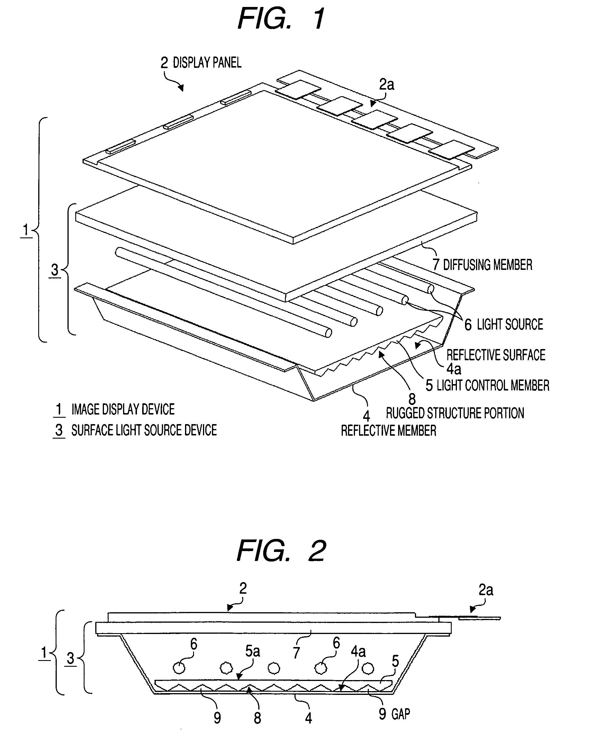
FIG. 1 is an exploded perspective view showing a structure of an image display device according to the invention, and FIG. 2 is a side view showing the structure of the image display device.

An image display device 1 roughly includes a display panel 2 which displays images and a surface light source device 3 which emits light to the display panel 2. When the image display device 1 is a liquid crystal display device, the display panel 2 will be a liquid crystal panel, and the surface light source device 3 will be a backlight.

The image display device 1 has a structure in which respective necessary portions are arranged inside a not-shown outer casing. In this case, the outer casing is formed to be flat in the front-and-back direction as well as to have a box shape which opens forward, and the display panel 2 is disposed at a position where the panel blocks the opening from the inside. The display panel 2 has a structure, for example, in which a transmissive color liquid crystal panel i...


PUM


Abstract

A surface light source device includes a diffusing member which diffuses light, a reflective member which reflects light, plural light sources provided aligned in a flat manner between the diffusing member and the reflective member, and a light control member provided between the plural light sources and the reflective member as well as arranged in a state that a gap is imposed between the reflective member and the light control member, which has a light-guiding function of guiding part of light emitted from respective light sources in an alignment direction of the light sources, in which the light control member has a rugged structure portion in which geometric shapes in cross section are continuously formed on at least one surface.

Description

BACKGROUND OF THE INVENTION1. Field of the InventionThe present application claims priority from Japanese Patent Application No. JP 2008-107486 filed in the Japanese Patent Office on Apr. 17, 2008 and Japanese Patent Application No. JP 2008-190601 filed in the Japanese Patent Office on Jul. 24, 2008, the entire contents of which are incorporated herein by reference.The present invention relates to a surface light source device irradiating light and an image display device using the same.The present invention relates to a surface light source device irradiating light and an image display device using the same.2. Description of the Related ArtThere exists a surface light source device performing illumination by using light sources such as a cold cathode fluorescent lamp (CCFL) and a light emitting diode (LED). The surface light source device is used for, for example, lighting equipment by using the light source as illumination directly, or used for image display devices such as a tele...

Claims


Application Information

Patent Timeline
Patent Type & Authority Patents(United States)
IPC IPC(8): G09F13/08
CPCG02F1/133606G02F1/133604G02F2001/133607G02F1/133607
Inventor ITO, ATSUSHIKOUYAMA, YOSHIAKI
Owner SONY CORP
Why Eureka
Try Eureka