Surface light source device and image display device

a light source device and surface light source technology, applied in the field of surface light source devices and image display devices, can solve the problems of increasing costs, reducing light use efficiency, and high cost of optical films, and achieves the effects of reducing the number of light sources, shortening the distance between light sources, and low cos

Inactive Publication Date: 2009-10-22
SONY CORP
View PDF3 Cites 6 Cited by
  • Summary
  • Abstract
  • Description
  • Claims
  • Application Information

AI Technical Summary

Benefits of technology

[0016]According to the embodiment of the invention, the light control member is inserted between plural light sources and the reflective member, and the rugged structure portion in which geometric shapes in cross section are formed continuously is provided on at least one surface of the light control member, thereby allowing the light control member to have the light-guiding function and thereby guiding light between plural light sources (intermediate position) by us

Problems solved by technology

However, since this kind of optical film is generally expensive, the costs increase.
Additionally, since light sequentially passes through the plural optical films in actual fact, use efficiency of light decreases.
Accordingly, there is a problem that, for example, slight displacement of lamps is recognized as unevenness of display.
Therefore, th

Method used


Image

  • Surface light source device and image display device
  • Surface light source device and image display device
  • Surface light source device and image display device

Examples


first embodiment

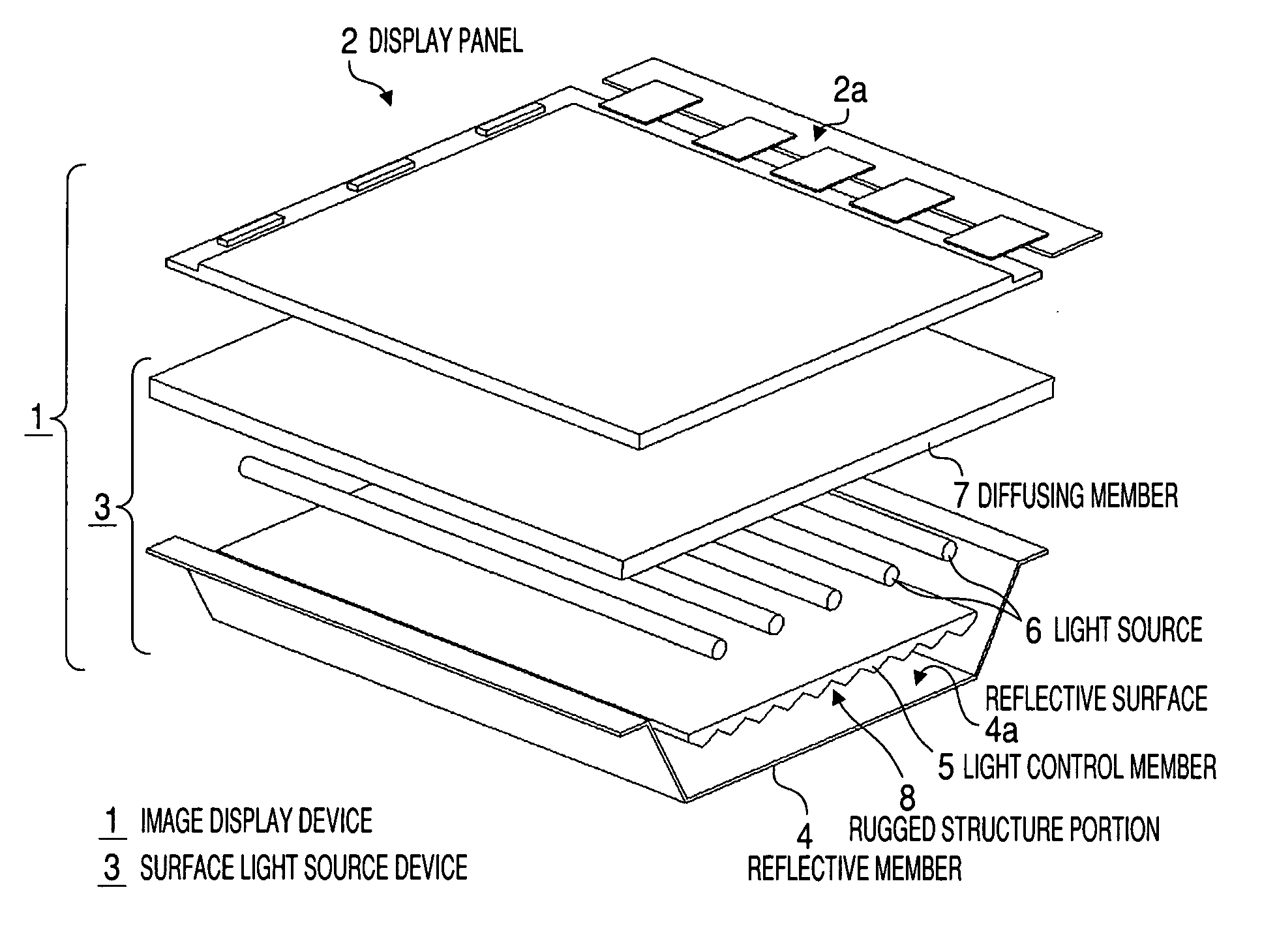
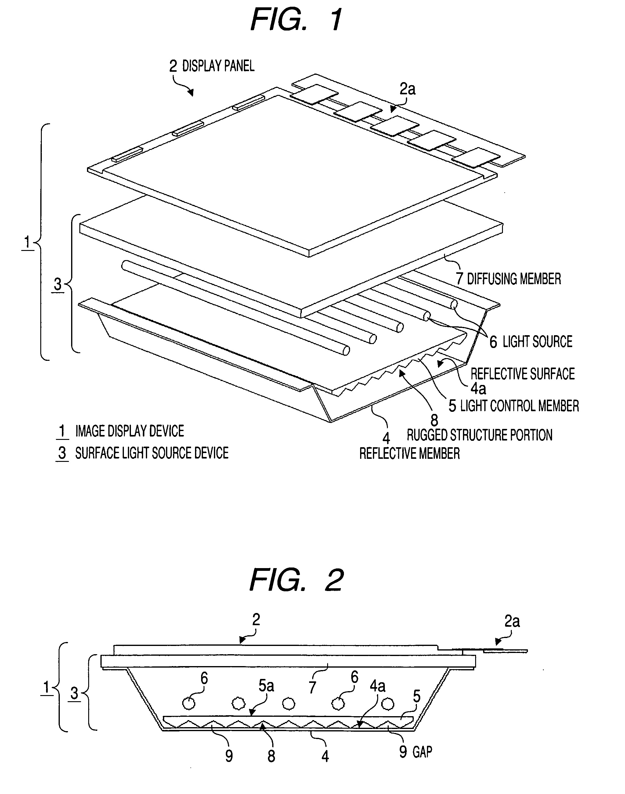
[0049]FIG. 1 is an exploded perspective view showing a structure of an image display device according to the invention, and FIG. 2 is a side view showing the structure of the image display device.

[0050]An image display device 1 roughly includes a display panel 2 which displays images and a surface light source device 3 which emits light to the display panel 2. When the image display device 1 is a liquid crystal display device, the display panel 2 will be a liquid crystal panel, and the surface light source device 3 will be a backlight.

[0051]The image display device 1 has a structure in which respective necessary portions are arranged inside a not-shown outer casing. In this case, the outer casing is formed to be flat in the front-and-back direction as well as to have a box shape which opens forward, and the display panel 2 is disposed at a position where the panel blocks the opening from the inside. The display panel 2 has a structure, for example, in which a transmissive color liqu...

second embodiment

[0087]FIG. 17 is a sectional side view in which part of the rugged structure portion 8 of the light control member 5 applied in the invention is enlarged. As shown in the drawing, a cross-sectional shape of the convex portion in the rugged structure portion 8 is a triangular shape. Convex portions and concave portions in the rugged structure portion 8 are formed including a first slope 14a, a second slope 14b, a third slope 14c and a fourth slope 14d respectively having different inclination angles θ1, θ2, θ3, and θ4 with respect to a reference axis 13. The first slope 14a inclines with respect to the reference axis 13 at the angle θ1 and the second slope 14b inclines with respect to the reference axis 13 at the angle θ2. The third slope 14c inclines with respect to the reference axis 13 at the angle θ3 and the fourth slope 14d inclines with respect to the reference axis 13 at the angle θ4. The “reference axis” described in the specification indicates an axis which is perpendicular ...

third embodiment

[0111]In the invention, it is possible to fix the light control member 5 integrally with the reflective member 4 and the casing 41 by using the fixing members 40. Additionally, the expand / contract portions 46 are locked at the outer surface of the casing 41 in the state in which the base portion 42 of the fixing member 40 bites the light control member 5, therefore, it is possible to prevent the fixing member 40 from resonating due to the effect of vibration of a speaker and the like or generating abnormal noise. Additionally, the piercing holes 51, 52 and 53 provided at the casing 41, the reflective member 4 and the light control member 5 are completely filled by the lid portions 42a. Therefore, it is possible to prevent foreign substances from getting into the surface light source device 3 through the piercing holes 51, 52 and 53. In the case that the base portion 42 bites the light control member 5 to a degree that the rugged structure portion 8 of the light control member, is fl...


PUM


Abstract

A surface light source device includes a diffusing member which diffuses light, a reflective member which reflects light, plural light sources provided aligned in a flat manner between the diffusing member and the reflective member, and a light control member provided between the plural light sources and the reflective member as well as arranged in a state that a gap is imposed between the reflective member and the light control member, which has a light-guiding function of guiding part of light emitted from respective light sources in an alignment direction of the light sources, in which the light control member has a rugged structure portion in which geometric shapes in cross section are continuously formed on at least one surface.

Description

BACKGROUND OF THE INVENTION[0001]1. Field of the Invention[0002]The present invention relates to a surface light source device irradiating light and an image display device using the same.[0003]2. Description of the Related Art[0004]There exists a surface light source device performing illumination by using light sources such as a cold cathode fluorescent lamp (CCFL) and a light emitting diode (LED). The surface light source device is used for, for example, lighting equipment by using the light source as illumination directly, or used for image display devices such as a television receiver and a personal computer by using the light source as backlight illumination.[0005]As the above image display device, for example, a liquid crystal display device using a liquid crystal panel as a display panel on which images are displayed can be cited. Since the liquid crystal panel is not a self-luminous type display in the liquid crystal display device, a surface light source device irradiating...

Claims


Application Information

Patent Timeline
IPC IPC(8): G02F1/13357F21V1/00
CPCG02F1/133604G02F2001/133607G02F1/133606G02F1/133607
Inventor ITO, ATSUSHIKOUYAMA, YOSHIAKI
Owner SONY CORP
Why Eureka
Try Eureka