Method for the production of a rotor winding for an electric machine

a technology of electric machines and winding heads, which is applied in the direction of stator/rotor bodies, synchronous machines with rotating armatures, stationary magnets, etc., can solve the problems of reducing the service life or durability of the motor, and increasing the wear and tear of the carbon brushes. , to achieve the effect of reducing the radial acting force excitation at the rotor, reducing the radial acting force, and increasing the length of the connecting

Active Publication Date: 2011-12-20
ROBERT BOSCH GMBH
View PDF9 Cites 9 Cited by
  • Summary
  • Abstract
  • Description
  • Claims
  • Application Information

AI Technical Summary

Benefits of technology

[0124]The foregoing relates to a preferred exemplary embodiment of the invention, it being understood that other variants and embodiments thereof are possible within the spirit and scope of the invention, the latter being defined by the appended claims.
Wf(j)=cos 2π*p / z*(j−Lai / M),

Problems solved by technology

In such machines, the rotor current is not distributed to two coil lanes, but instead, because of the contact bridges, to four coil lanes, with the disadvantage that per coil lane, only half as many coils are connected in series.
This causes greater wear of the carbon brushes on the commutator and thus a correspondingly limited service life or durability of the motor.
This causes greater cantilevering of the winding heads and leads to long winding head connections of the coils, which are expensive in terms of material and also cause high heat losses.
This embodiment has the disadvantage that because of an increased lamination voltage, with five coils instead of twelve, an increased brush fire occurs, which impairs the service life of the commutator and hence also the durability of the machine.

Method used


Image

  • Method for the production of a rotor winding for an electric machine
  • Method for the production of a rotor winding for an electric machine
  • Method for the production of a rotor winding for an electric machine

Examples


Embodiment Construction

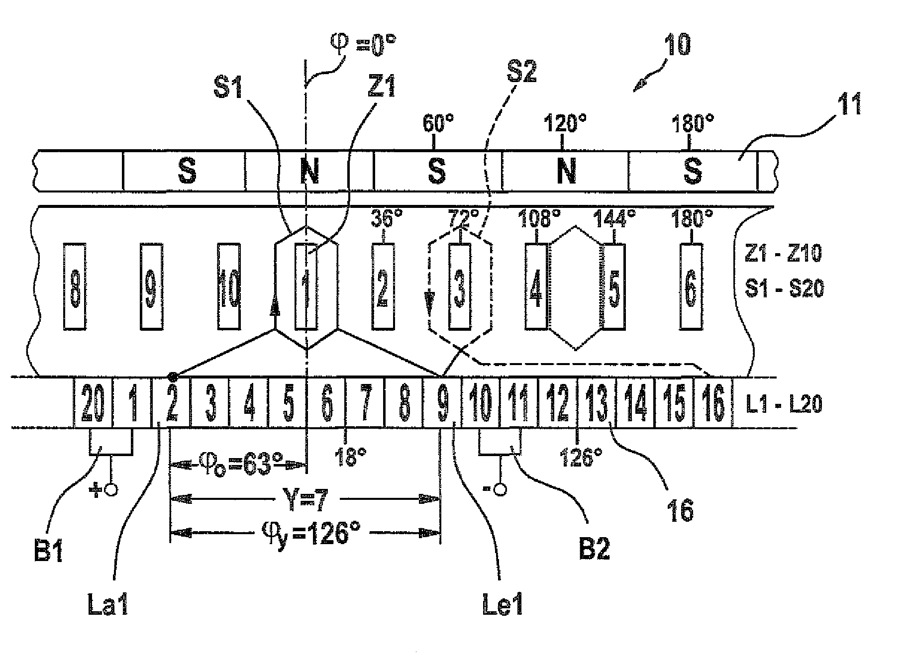
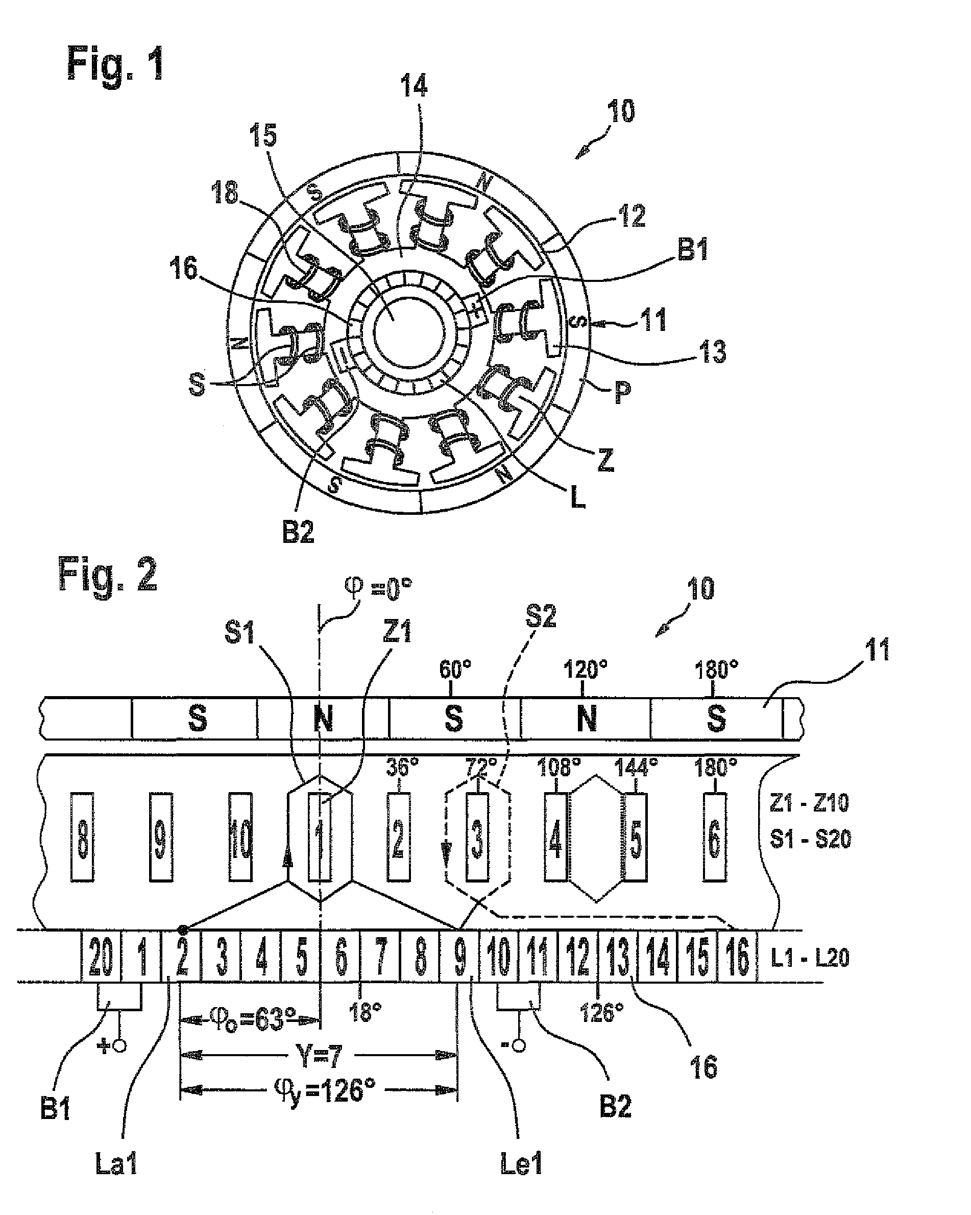
[0027]In FIG. 1, for a first exemplary embodiment, a permanent-magnetically excited six-pole direct current motor, as an electric machine, is schematically shown in front view and marked 10. Such machines are preferentially used for control drives, blowers, and the like in motor vehicles and must function reliably under heavy loads, if at all possible over the entire service life of the vehicle. Accordingly, their construction must be as robust as possible. The electric machine has a six-pole stator 11, which cooperates across a working air gap 12 with a commutator rotor 13, hereinafter called the rotor. The rotor 13 comprises a lamination packet 14, which is secured to a rotor shaft 15 that is supported on both ends. Ten pole teeth Z distributed uniformly are disposed on the circumference of the lamination packet 14, and between each of them, slots are embodied for receiving a total of twenty coils S of a rotor winding 18. The coils S are produced as single-tooth coils in pairs, ea...


PUM

PropertyMeasurementUnit
angle erroraaaaaaaaaa
widthaaaaaaaaaa

Abstract

The invention relates to a method for producing the rotor winding of an electric machine comprising at least four exciter poles in the stator and a commutator rotor with a number of pole teeth which deviates from the number of exciter poles as well as a number of individual tooth coils and commutator segments that is at least twice as large as the number of pole teeth. In order to obtain low torque ripple and a long service life by optimally commutating the coils, a first coil is wound from an initial segment at a selectable offset angle to the initial segment on a first pole tooth, the winding wire is then fixed to another commutator segment at a predefined segment interstice length, whereupon a coil is successively wound from each segment onto the pole tooth having the lowest angular error relative the offset angle in relation to the pole separation of the stator, and the winding wire is then contacted on another segment at the same segment interstice length.

Description

CROSS-REFERENCE TO RELATED APPLICATION[0001]This application is a 35 USC 371 application of PCT / EP 2005 / 055718 filed on Nov. 3, 2005.BACKGROUND OF THE INVENTION[0002]1. Field of the Invention[0003]The invention relates to a method for producing the rotor winding of an electric machine and to an electric machine having a rotor winding produced by this method.[0004]2. Description of the Prior Art[0005]From German Patent DE 197 57 279 C1, it is known, in a four-pole electric motor, to use a commutator rotor with 12 commutator laminations and 12 coils connected to them, in order to attain low torque waviness and good commutation. The laminations that are diametrically opposed to one another are connected to one another via contact bridges, in order to make the current supply to the rotor symmetrical and to assure it with only one pair of brushes. In such machines, the rotor current is not distributed to two coil lanes, but instead, because of the contact bridges, to four coil lanes, wit...

Claims


Application Information

Patent Timeline
Patent Type & Authority Patents(United States)
IPC IPC(8): H02K15/095
CPCH02K23/30H02K3/28Y10T29/49012H02K15/0478H02K15/06
Inventor ROOS, GERALD
Owner ROBERT BOSCH GMBH
Why Eureka
Try Eureka