Method for resolving overloads in autorouting physical interconnections

a physical interconnection and overload technology, applied in the direction of electric digital data processing, instruments, computing, etc., can solve the problems of a geometric router's path resolution procedure not being able to create a drc geometric solution based on a candidate topological solution, computationally intensive and therefore difficult to solve, and potentially complex shapes in a geometrically defined routing space can be moved in a geometrically defined routing space. , the problem of computational complexity and complexity,

Active Publication Date: 2011-12-20
CADENCE DESIGN SYST INC
View PDF8 Cites 3 Cited by
  • Summary
  • Abstract
  • Description
  • Claims
  • Application Information

AI Technical Summary

Problems solved by technology

Unfortunately, moving potentially complex shapes in a geometrically defined routing space can be computationally intensive and therefore, extremely slow.
Overloads that are not eliminated immediately after the path finding procedures have completed execution are more difficult to resolve in later routing stages.
Moreover, the path resolution procedures of a geometric router might not be able to create a DRC geometric solution based on a candidate topological solution in which overloads still exist.
Currently, topological autorouting is limited to single-layer applications, where there are no vias (conductive elements electrically coupling different layers).
Since vias are not used in single-layer applications, there are few, if any, opportunities to execute shoves to resolve overloads.
Previously, the only technique available to remove overloads in single-layer applications was to effect a reroute of the circuit with an increased penalty imposed for subsequent routing the path in the overloaded region.
The technique works, however, rerouting involves inherently slow path finding routines.
Generally, for multi-layer routing, high completion rates cannot be achieved efficiently without applying shoving operations to vias.

Method used


Image

  • Method for resolving overloads in autorouting physical interconnections
  • Method for resolving overloads in autorouting physical interconnections
  • Method for resolving overloads in autorouting physical interconnections

Examples


Embodiment Construction

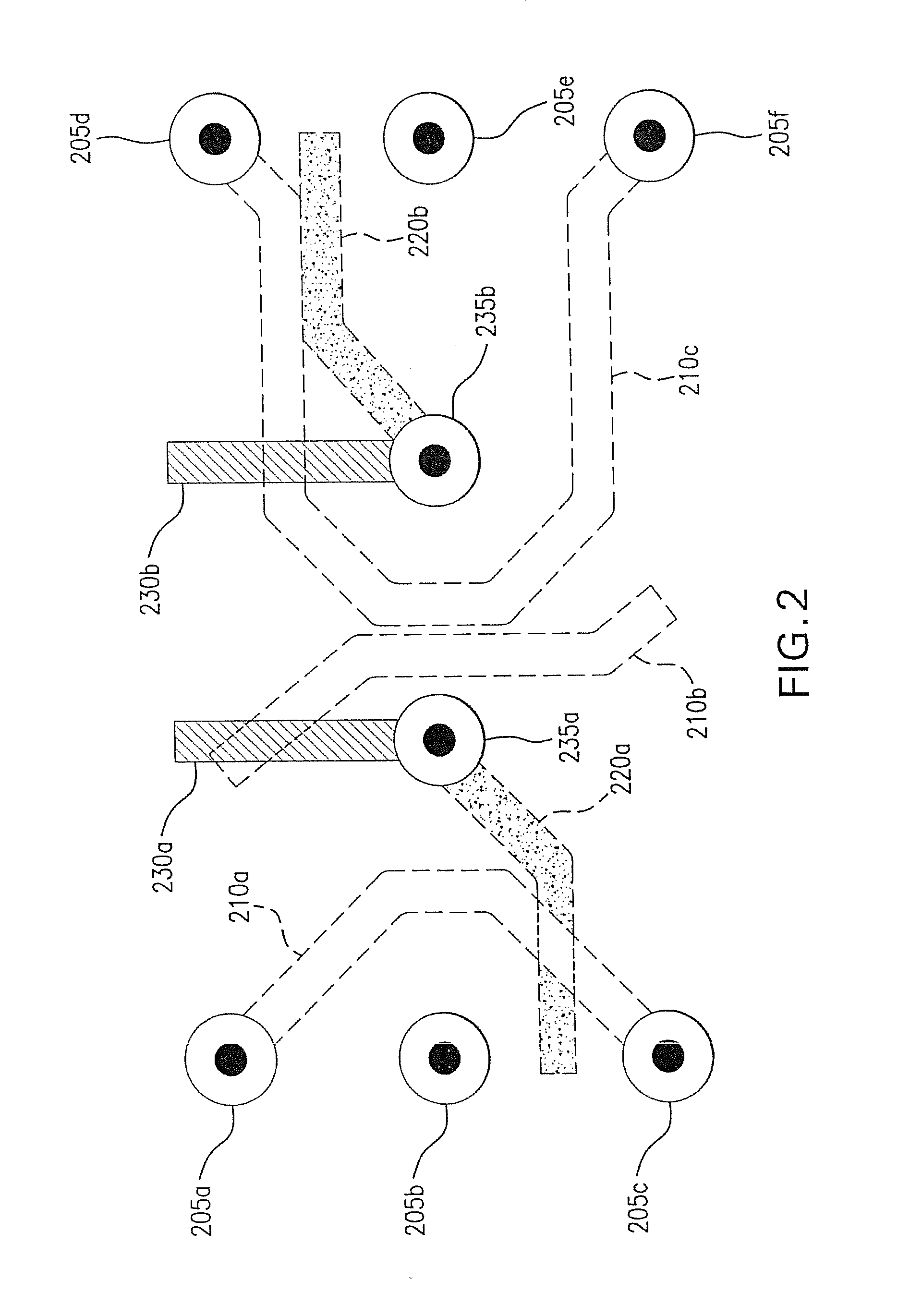
[0026]The circuit routing field has an associated set of teens, several of which will now be defined for purposes of clarity. As used herein, “terminal” is a fixed routable circuit element establishing the beginning or end of an electrical connection. Terminals include pads or pins associated with circuit components, such as integrated circuit packages, and vias, which are conductors, often formed as plated through-holes, completing electrical connections between circuit layers. A “net” is a collection of terminals, all of which are, or must ultimately be, electrically connected to one another by an associated conductive trace. A “rat” defines a connection from one terminal of a net to another. A rat may connect connection points that lie on different circuit layers, whereas a “ratline” is such a connection that is confined to a single circuit layer. The objective of an autorouter is to electrically connect the terminals of a net in the order specified by the rats.

[0027]Terminology ...


PUM


Abstract

Overloaded regions in the routing space of a physical network are resolved via a routing procedure composed of a topological routing phase and a geometric routing phase. The overloads are resolved in the topological routing phase where the constraints of routing are less prohibitive. Multiple topological transformations directed toward resolving the overloads are executed in the topological routing phase prior to a geometric arrangement being realized. The topological transformations may be applied concurrently by way of a multi-threaded embodiment of the invention.

Description

RELATED APPLICATIONS[0001]This application is a Divisional patent application of co-pending application Ser. No. 12 / 325,535, filed on 1 Dec. 2008 which is a Continuation patent application of application Ser. No. 11 / 339,562, filed on 26 Jan. 2006, now U.S. Pat. No. 7,464,358. The entire disclosure of the prior application Ser. No. 12 / 325,535, from which an oath or declaration is supplied, is considered a part of the disclosure of this Divisional application and is hereby incorporated by reference.BACKGROUND OF THE INVENTION[0002]1. Field of the Invention[0003]The invention disclosed herein is related to the determination of interconnections or paths between terminals of interoperable components. More specifically, the invention is related to resolving layout congestion in a routing or path-finding phase during which spatial restrictions otherwise imposed are temporarily suspended. Such methodology is applicable in such fields as automatic circuit path routing, or autorouting, of pri...

Claims


Application Information

Patent Timeline
Patent Type & Authority Patents(United States)
IPC IPC(8): G06F17/50
CPCG06F17/5077G06F30/394
Inventor WADLAND, KENSCHILP, WILLIAM
Owner CADENCE DESIGN SYST INC
Why Eureka
Try Eureka